High-speed, high-precision applications frequently experience premature mechanical failure when subjected to combined axial and radial loads without the correct bearing architecture. Specifying the right bearing requires an exact balance of contact angles, precision grades, and preload configurations. Miscalculations lead to catastrophic machinery downtime, thermal seizing, and inflated maintenance costs. Engineers and procurement teams must navigate complex geometric tolerances and material science variables to ensure operational reliability. This guide breaks down the technical specifications, procurement drivers, and evaluation frameworks necessary to confidently specify and procure the correct Angular Contact Ball Bearing for demanding industrial applications. We will examine raceway mechanics, preload implementation, and failure mitigation strategies to optimize your rotating equipment.
- Load Capacity is Dictated by Contact Angle: Higher contact angles support greater axial loads but inherently reduce maximum radial capacity and rotational speed limits.
- Precision Drives Both Performance and Price: Precision grades (e.g., ISO P0 to P2) directly correlate with operational accuracy, vibration reduction, and unit cost.
- Preload is a Critical Failure Point: Establishing the correct preload configuration is essential for system rigidity; incorrect preload is a primary cause of premature bearing fatigue and thermal failure.
Understanding the Angular Contact Ball Bearing Architecture
The mechanics of the asymmetrical raceway allow these bearings to handle complex loads. The offset inner and outer ring raceways accommodate simultaneous radial and unidirectional axial loads. This design ensures that forces transfer efficiently across the rolling elements. When a load is applied, the internal geometry forces the balls to contact the inner and outer raceways at a specific angle relative to the radial plane. This asymmetrical design is what separates them from standard deep groove variants, which are primarily built for radial loads with only incidental axial capacity.
The physics of the contact angle dictate how the line of action through the balls transfers force. This angle fundamentally alters load distribution. By shifting the load path, the bearing supports heavy thrust forces while maintaining radial stability. The contact ellipse—the actual area of deformation where the ball meets the raceway under load—changes shape and position based on this angle. A larger angle pushes the contact ellipse higher up the raceway shoulder, which is why the shoulder on one side of the inner and outer rings is raised. This raised shoulder provides the necessary material support to prevent the ball from overriding the raceway under heavy axial thrust.
In field applications, understanding this architecture is necessary for diagnosing premature wear. If a bearing designed for a 15-degree contact angle is subjected to the axial loads meant for a 40-degree bearing, the contact ellipse will truncate against the edge of the raceway. This truncation causes massive stress concentrations, leading to rapid spalling and eventual catastrophic failure of the rolling elements. Therefore, matching the internal geometry to the exact load vectors of the application is the first step in bearing specification.
Categorizing Angular Contact Ball Bearings by Design
Single-Row Angular Contact Ball Bearings
These bearings are ideal for high-speed applications requiring support for unidirectional axial loads alongside radial loads. They provide excellent performance in precision machinery where space allows for dedicated single-direction thrust support. Because they can only accommodate axial loads in one direction, they are almost never used in isolation unless the application guarantees a constant, unidirectional thrust load that keeps the balls seated against the raceway shoulders.
Duplex pairing configurations are often necessary to achieve bidirectional load handling and specific rigidity profiles. Engineers evaluate configurations based on the required stiffness and load distribution. The three primary pairing arrangements are:
- Back-to-Back (DB): The load lines diverge toward the shaft axis. This arrangement provides high rigidity and excellent resistance to overturning moments, making it ideal for unsupported shaft ends.
- Face-to-Face (DF): The load lines converge toward the shaft axis. This setup is more forgiving of misalignment but offers less resistance to moment loads.
- Tandem (DT): The load lines are parallel. This configuration shares heavy unidirectional axial loads across both bearings but requires a third bearing to handle any reverse axial forces.
Double-Row Angular Contact Ball Bearings
A double-row design is preferred as a space-saving alternative to paired single-row bearings. This configuration consolidates two single-row bearings into one unit, simplifying assembly in constrained environments. They essentially function like a pair of single-row bearings mounted back-to-back but take up less axial space on the shaft and in the housing.
However, there are compromises in overall rigidity and load capacity when choosing a double-row unit over a dedicated duplex pair. The internal geometry often restricts the maximum load capacity compared to matched single-row bearings. Furthermore, double-row bearings typically have a fixed internal clearance or preload set at the factory, which limits the engineer's ability to fine-tune the system rigidity during installation. They are highly effective for pumps, compressors, and gearboxes where space is at a premium, but they may not offer the extreme stiffness required for machine tool spindles.
Four-Point Contact Ball Bearings
These bearings support applications requiring bidirectional axial load support within a single row footprint. The split inner or outer ring allows the bearing to handle thrust loads in both directions without needing a paired setup. The unique gothic arch raceway profile creates four points of contact between the ball and the raceways under pure radial load, though under axial load, this shifts to a standard two-point contact.
Strict limitations exist regarding radial load dominance and speed constraints inherent to four-point designs. They are primarily thrust bearings and should not be subjected to heavy radial loads. If the radial load becomes too high relative to the axial load, the balls will maintain four points of contact, causing severe friction, heat generation, and rapid wear. They are best utilized in applications where axial loads dominate and space constraints prevent the use of a double-row or duplex pair.
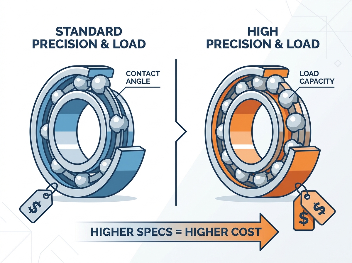
Technical Evaluation Dimensions: Specifications That Drive Performance
Contact Angle Selection (15°, 25°, 40°)
A 15° contact angle focuses on high speed. Specify this for machine tool spindles and applications where rotational speed and radial stiffness take precedence over axial capacity. The lower angle minimizes the centrifugal forces acting on the balls, reducing internal friction and allowing for exceptionally high RPMs without excessive heat generation.
A 25° to 30° contact angle provides a balanced load profile. Evaluate this range for general-purpose precision machinery requiring a balance of speed and axial support. This mid-range angle is common in applications where the shaft experiences moderate thrust loads but still needs to maintain relatively high rotational speeds.
A 40° contact angle focuses on heavy axial loads. Recommend this for high-thrust applications like industrial pumps and compressors where axial load dominance is the primary success criterion. The steep angle maximizes the bearing's ability to support thrust forces, though it significantly reduces the maximum allowable speed due to increased ball sliding and friction.
Decoding manufacturer angle codes prevents procurement errors. Reference the table below to map physical angles to standard industry nomenclature. Note that different manufacturers may use slight variations of these suffixes, so always verify against the specific brand's technical catalog.
| Contact Angle | Common Suffix Codes | Primary Application Focus | Speed Capability |
| 15° | C | High Speed, High Radial Rigidity | Maximum |
| 25° - 30° | AC, A5 | Balanced Speed and Load | Moderate |
| 40° | B | Heavy Axial Load | Low |
Precision Grades and Tolerances (ISO/ABEC)
Standard industrial grades (ISO P0/ABEC-1, ISO P6/ABEC-3) and intermediate grades (ISO P5/ABEC-5) serve general applications. Super-precision requirements demand ISO P4/ABEC-7 or ISO P2/ABEC-9 for critical operations. These grades define the allowable dimensional deviations in the bearing's bore, outer diameter, and width, as well as the running accuracy (radial and axial runout).
Justify the cost premium of higher precision grades in CNC machining, aerospace, and robotics where runout tolerances are unforgiving. Higher precision reduces vibration and heat generation at high speeds. When a shaft rotates at 20,000 RPM, even a few microns of runout can cause severe vibration, leading to poor surface finish on machined parts and rapid degradation of the bearing itself. Selecting the correct precision grade requires analyzing the maximum allowable runout at the tool tip or shaft end.
Cage Materials and Design
Polyamide or resin cages offer low friction, quiet operation, and high-speed capabilities. Note their strict operating temperature limits, which typically cap around 120°C. These cages are lightweight, which reduces centrifugal forces and allows for better grease retention. However, they can degrade rapidly if exposed to certain synthetic lubricants or extreme heat.
Machined brass cages provide high strength, extreme vibration resistance, and durability in harsh environments. They excel in heavy-duty applications where shock loads occur. Brass cages are often guided by the inner or outer ring rather than the rolling elements, which provides superior stability at high speeds, though they add significant weight and inertia to the bearing assembly.
Stamped steel cages serve as the standard, cost-effective solution for general industrial use. They handle moderate speed requirements and offer good temperature resistance. While not suitable for ultra-high-speed spindles, stamped steel cages are robust and reliable for pumps, conveyors, and standard electric motors.
Preload and Rigidity: The Critical Success Factors
Preload Classes and Impact
Preload classes break down into Light, Medium, and Heavy categories. Their function is to eliminate internal clearance to prevent ball skidding and ensure precise shaft positioning. By applying a permanent axial load to the bearing pair, preload forces the balls into constant contact with the raceways, eliminating any play or backlash in the system.
The trade-off matrix maps the inverse relationship between system rigidity and operational friction. Higher preload increases rigidity but also increases heat generation and lowers speed limits. A heavy preload is necessary for applications requiring extreme stiffness, such as heavy milling operations, but it will severely restrict the maximum RPM of the spindle. Conversely, a light preload allows for high-speed operation but may result in unacceptable deflection under heavy cutting loads.
Preload Implementation Methods
Spring-loaded mechanisms absorb thermal expansion and maintain consistent force. Solid or locknut-adjusted preload maximizes system rigidity but risks thermal runaway if temperatures spike and expand the shaft. Spring preload uses coil or wave springs to apply a constant axial force against the outer ring of one bearing. This method is highly effective for high-speed spindles where thermal expansion of the shaft would otherwise cause a rigid preload to spike dangerously high.
Universally matchable bearings with factory-set preload offer high reliability. Compare this against the risks of manual adjustment via shims or torque tuning during installation, which requires precise skill. Factory-set bearings are ground to exact tolerances so that when they are clamped together, the desired preload is automatically achieved. Manual shimming requires the technician to measure the gap between the bearings and insert precision shims to achieve the correct preload, a process prone to human error and contamination.
Procurement Factors: What Determines the Cost of an Angular Contact Ball Bearing?
Material selection drives the cost delta between standard bearing steel (52100) and hybrid ceramic balls (Silicon Nitride). Ceramic balls are used for high-speed or electrical insulation requirements. Because silicon nitride is significantly harder and lighter than steel, it reduces centrifugal forces and internal friction, allowing for higher speeds and lower operating temperatures. The manufacturing process for aerospace-grade ceramic balls is highly complex, which directly impacts the procurement cost.
The precision cost curve explains the exponential increase in manufacturing difficulty. Moving from P0/P6 up through intermediate P5 to super-precision P4 and P2 significantly impacts the manufacturing time and rejection rates. Achieving P2 tolerances requires specialized grinding equipment and climate-controlled manufacturing environments to prevent thermal expansion during the machining process.
Specifying Tier 1 manufacturers carries procurement implications. Proven quality assurance and traceability command a premium over economy brands. Tier 1 manufacturers invest heavily in research and development, raw material inspection, and automated quality control. This ensures that every bearing meets the stated specifications, reducing the risk of premature failure in critical applications.
Specialized greases, custom contact angles, and proprietary cage designs inflate initial procurement costs. Customization requires specialized manufacturing runs and engineering support. For example, specifying a bearing with a specialized high-speed grease fill and a PEEK (Polyether ether ketone) cage for high-temperature operation will require a custom order, increasing lead times and manufacturing expenses.
Implementation Risks and Mitigation Strategies
Incorrect mounting orientation in paired configurations leads to immediate failure. Visually identify the thrust face of the outer ring to ensure proper installation alignment. The thrust face is typically the wider shoulder of the outer ring. If a bearing designed to take thrust in one direction is installed backward, the balls will ride up over the low shoulder, destroying the cage and the raceway within minutes of operation.
Operating temperatures can alter internal preload dynamically. Calculate thermal expansion to avoid risking thermal runaway and seizing if not accounted for in the design phase. When a shaft heats up faster than the housing, it expands radially and axially. In a rigidly preloaded system, this expansion increases the internal load on the bearings, generating more heat, which causes more expansion. This vicious cycle, known as thermal runaway, ends in catastrophic bearing seizure.
Select the correct grease volume and viscosity based on the specific contact angle, cage type, and operating speed. Proper lubrication prevents starvation and churning, which generate excessive heat. Over-greasing a high-speed bearing is a common field error. Too much grease causes the rolling elements to churn the lubricant, generating massive amounts of fluid friction and heat. For high-speed applications, a grease fill of 15% to 20% of the free internal space is typically recommended, whereas lower-speed applications may require a 30% to 50% fill.
Contamination control during installation is another critical mitigation strategy. Angular contact bearings, especially super-precision variants, are highly sensitive to particulate contamination. A single piece of dirt or metal shaving introduced during mounting can dent the raceway, leading to elevated vibration and premature fatigue spalling. Always install bearings in a clean environment, leave them in their original packaging until the exact moment of installation, and use proper induction heaters rather than open flames or brute force to mount them on the shaft.
Conclusion
The optimal angular contact ball bearing is always a calculated compromise between load direction, rotational speed, and required system rigidity. By understanding the mechanical limitations and performance drivers of these components, you can eliminate premature failures and optimize machinery uptime.
- Calculate your exact axial and radial load ratios to determine the necessary contact angle.
- Select the appropriate precision grade based on the maximum acceptable runout for your specific application.
- Determine the optimal preload method (spring vs. rigid) and configuration (DB, DF, DT) to balance rigidity with thermal stability.
- Finalize cage materials and lubrication specifications based on operating temperatures and environmental contaminants.
- Consult with a bearing application engineer to verify your selection and request 3D CAD models for integration testing.
FAQ
Q: What is the exact difference between an angular contact ball bearing and a deep groove ball bearing?
A: Angular contact ball bearings have asymmetrical raceways designed to handle combined radial and unidirectional axial loads simultaneously. Deep groove ball bearings have symmetrical raceways and primarily handle radial loads, with limited axial capacity in both directions.
Q: How do I calculate and choose the correct contact angle for my specific load requirements?
A: Analyze the ratio of axial to radial loads. Use a 15° angle for high speeds and dominant radial loads, a 25° angle for balanced loads, and a 40° angle when heavy axial thrust is the primary force.
Q: What do precision grades like P5, P4, or ABEC-7 actually mean for bearing performance and lifespan?
A: Higher precision grades indicate tighter manufacturing tolerances for runout, bore, and outer diameter. This results in smoother rotation, less vibration, lower heat generation, and extended lifespan in high-speed applications.
Q: Can a single-row angular contact ball bearing support radial loads exclusively?
A: No. Applying a pure radial load induces an internal axial force due to the contact angle. They must be used in pairs or subjected to an external axial load to maintain proper ball-to-raceway contact.
Q: Why is preload necessary, and what happens if a bearing is over-preloaded?
A: Preload eliminates internal clearance, increases rigidity, and prevents ball skidding. Over-preloading causes excessive friction, rapid heat generation, premature wear, and potential thermal seizing.
Q: What is the correct procedure for mounting a duplex pair (Back-to-Back vs. Face-to-Face)?
A: Back-to-Back (DB) mounting places the load lines diverging toward the shaft axis, offering high moment rigidity. Face-to-Face (DF) mounting converges the load lines, tolerating more misalignment but offering less moment stiffness.
Q: How do spring-loaded preloads compare to rigid locknut preloads in high-temperature environments?
A: Spring preloads maintain a constant force and accommodate thermal expansion, making them safer for fluctuating temperatures. Rigid locknut preloads offer higher stiffness but risk thermal runaway if the shaft expands faster than the housing.

 English


