In high-performance machinery, the margin between optimal operation and catastrophic failure often comes down to internal load management and bearing selection. Engineers and system designers constantly evaluate mechanical components to ensure they meet exact operational demands. Specifying the wrong bearing type—specifically misjudging the balance between radial and axial loads—leads to premature wear, excessive thermal generation, spindle deflection, and costly unplanned downtime. A system is only as reliable as its weakest rotating component.
Resolving this engineering challenge requires a rigorous comparison between the versatile standard deep groove ball bearing and the highly specialized Angular Contact Ball Bearing. Standard radial bearings handle basic rotational tasks effectively, but complex machinery demands more sophisticated load distribution mechanisms. This guide breaks down the technical specifications, performance trade-offs, and implementation realities to drive accurate, application-specific procurement decisions.
Key Takeaways
- Load Handling Discrepancies: Standard ball bearings excel at managing heavy radial loads with minimal axial forces, whereas an angular contact ball bearing is explicitly engineered to support significant combined (simultaneous radial and unidirectional axial) loads.
- Standard Series Identifiers: Quick industry identification separates these parts: standard deep groove bearings typically fall under the 6000 series, while angular contact bearings belong to the 7000 series.
- The Contact Angle Trade-off: In angular contact designs, the specific contact angle (typically 15°, 25°, or 40°) dictates the operational limits; higher angles exponentially increase axial load capacity at the direct expense of maximum rotational speed.
- Rigidity and Preload: Angular contact bearings require precise preloading to maintain constant ball-to-raceway contact, offering superior system rigidity and high-speed stability compared to the inherent internal clearance of standard bearings.
- Installation Complexity: Transitioning to angular contact configurations introduces strict alignment tolerances and directional mounting requirements (such as cup-and-cone setups), increasing both installation complexity and the risk of improper assembly.
Core Design Principles: Geometry, Nomenclature, and Load Distribution
Standard (Deep Groove/Radial) Ball Bearings: The Versatile Baseline (6000 Series)
Standard ball bearings utilize a symmetrical raceway design with deep groove profiles. This geometry allows the balls to sit securely within the inner and outer rings, providing a stable platform for rotation. The internal clearance within these bearings accommodates slight thermal expansion and minor misalignment during operation. Industry professionals universally identify these components through the 6000 Series nomenclature, which dictates standardized dimensions and load ratings across global manufacturers.
The mechanics of radial load distribution in a standard bearing rely on transferring forces perpendicular to the shaft. The load spreads across the ball complement located directly in the load zone. However, this symmetrical design presents distinct limitations when handling axial or thrust loads. The raceway shoulder height restricts the amount of lateral force the bearing can withstand. Excessive axial loads push the balls against the edge of the raceway, creating a pinch risk that rapidly degrades the bearing material and leads to premature failure. When you tear down a failed standard bearing subjected to high thrust, you will typically see a distinct wear path riding dangerously close to the raceway edge, often accompanied by spalling or cage fracture.
To understand the operational limits of standard bearings, we must look at internal clearance classes. These clearances dictate how much radial play exists before the bearing is mounted and reaches operating temperature.
| Clearance Class | Internal Play | Primary Application | Thermal Expansion Tolerance |
| CN (Normal) | Standard | General electric motors, standard gearboxes | Low to Moderate |
| C3 | Greater than Normal | High-speed applications, moderate heat environments | High |
| C4 | Greater than C3 | Vibrating screens, extreme temperature applications | Very High |
The Angular Contact Ball Bearing: Engineered for Combined Loads (7000 Series)
Anatomical differences define the performance capabilities of the 7000 Series. These bearings feature asymmetrical raceway shoulders—one high and one low—specifically designed to transfer loads at a predetermined angle. This internal geometry shifts the contact points between the balls and the raceways, creating an angular line of force. This design is critical for applications where simultaneous radial and axial loads occur. The load path travels diagonally through the bearing, effectively distributing the stress across a larger surface area of the ball and raceway.
The traditional "cup and cone" design philosophy highlights the adjustable nature of these bearings. While classic setups allow for manual adjustment during installation, modern integrated angular contact cartridge bearings offer pre-set tolerances for simplified assembly. The mechanics ensure continuous ball-to-ring contact under operational loads. This constant engagement prevents the ball skidding and micro-vibrations common in standard bearings under thrust conditions, ensuring smooth rotation and extended component life. In high-speed spindle applications, this continuous contact is what prevents the balls from centrifugally skidding against the outer race, a phenomenon that causes rapid heat spikes and immediate lubricant breakdown.
When specifying these bearings, engineers must account for the specific contact angle. The angle is formed by the line connecting the points of contact between the ball and the raceways in the radial plane. This angle dictates the ratio of radial to axial load the bearing can support. A larger angle means higher axial capacity but lower radial capacity and reduced speed limits.
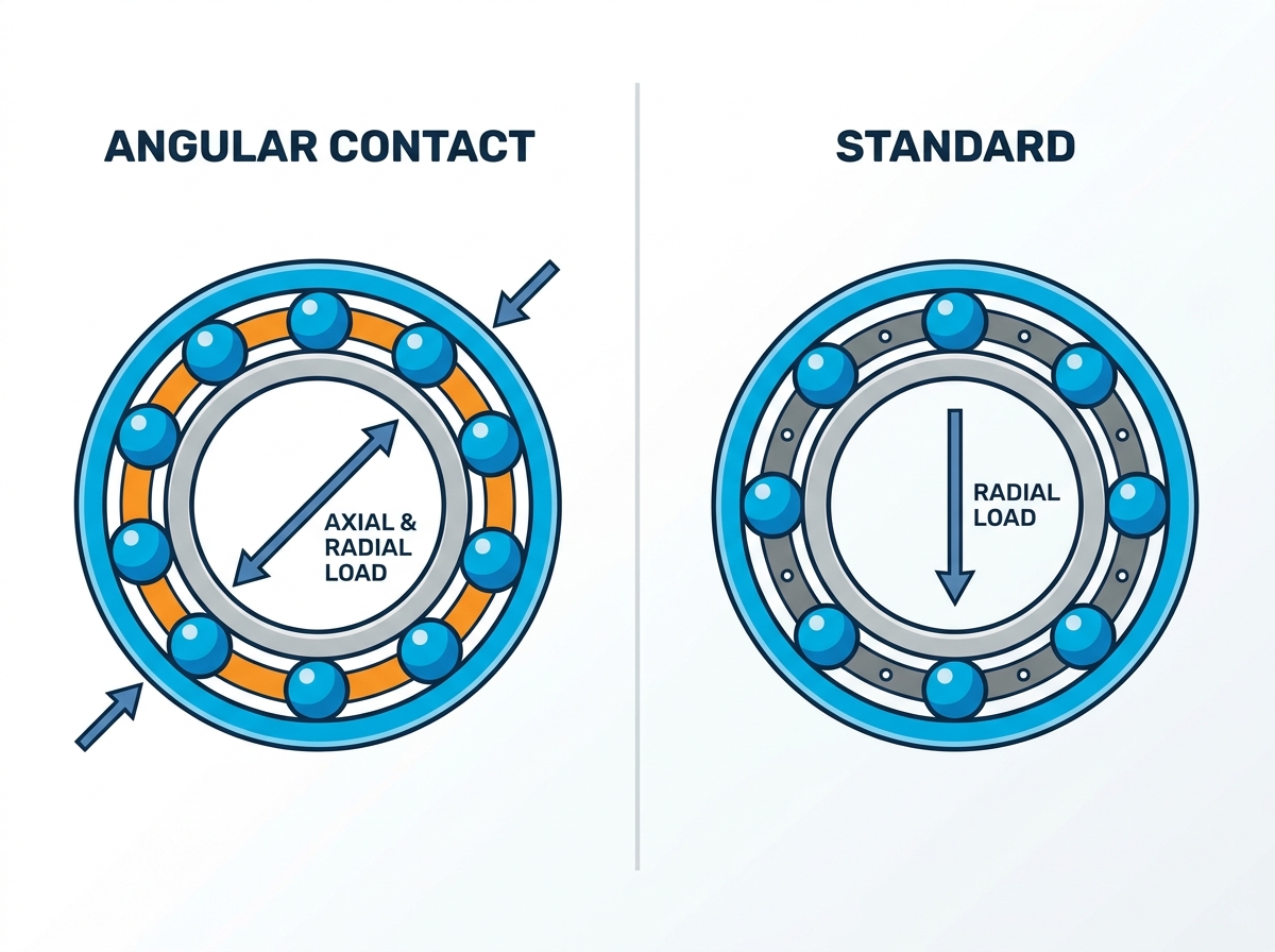
Technical Evaluation Dimensions: Feature-to-Outcome Mapping
Load Capacity and Directionality
Standard deep groove bearings offer bi-directional axial capacity, meaning they can handle light thrust loads from either direction. However, this capacity remains strictly limited to a fraction of their overall radial load rating. Pushing a standard bearing beyond this threshold compromises the raceway integrity. As a general rule of thumb in the field, if the axial load exceeds 10% of the radial load, a standard bearing will begin to experience accelerated wear.
Conversely, angular contact designs deliver high unidirectional axial capacity. The asymmetrical shoulder design channels thrust forces efficiently through the bearing structure. They must be subjected to an axial load to function correctly. Without this constant force, the balls may slide rather than roll, generating excessive friction and heat. This directional dependency dictates how engineers orient and mount these components within machinery. If you mount a single angular contact bearing without an opposing force (either from another bearing or a constant application load), the internal assembly will literally fall apart or skid to destruction within minutes of startup.
Contact Angles and Performance Trade-offs
The specific contact angle engineered into the bearing dictates its operational sweet spot. Selecting the correct angle requires balancing speed requirements against load demands. You cannot maximize both simultaneously; physics requires a compromise.
| Contact Angle | Primary Advantage | Limitation | Typical Application |
| 15° (Suffix C) | Ultra-high rotational speeds and high radial rigidity. | Lower axial load capacity. | Precision grinding spindles, high-speed routers. |
| 25° (Suffix E or A5) | Balanced performance for moderate speed and loads. | Not optimized for extreme extremes of speed or thrust. | General machinery, moderate-duty spindles. |
| 40° (Suffix B) | Maximized axial load capacity and shock resistance. | Significantly reduced maximum RPM capabilities. | Heavy-duty centrifugal pumps, agricultural gearboxes. |
Speed Ratings and Thermal Dynamics
Friction generation differs significantly between the two bearing types. The constant contact inherent in angular contact designs affects operating temperatures differently than the point-contact of standard radial bearings. While standard bearings might seem cooler under light loads, they struggle with heat generation when subjected to inappropriate axial forces. The moment a standard bearing takes a heavy thrust load, the balls ride up the raceway shoulder, changing the contact geometry from a point to an ellipse, which drastically increases friction.
The speed rating paradox reveals why angular contact bearings often achieve higher maximum speed ratings under combined loads. The non-stop ball-to-ring contact prevents centrifugal ball skidding and gyroscopic spinning, which are primary sources of heat and wear at extreme RPMs. Cage design materials further impact thermal expansion and speed limits. Polyamide and PEEK cages offer lower friction and better high-speed performance, while machined brass provides superior durability under harsh conditions and heavy vibrations. Steel cages are common but generally limited to lower speed applications due to their mass and centrifugal forces generated during rotation.
System Rigidity and Preload Requirements
System rigidity relies heavily on proper preloading. Preload is the intentional application of internal force to eliminate radial and axial play within the bearing assembly. Angular contact bearings utilize specific preload classes to achieve superior rotational accuracy and stiffness. A heavy preload maximizes rigidity for heavy cutting tools, while a light preload suits high-speed applications requiring lower operating temperatures.
This contrasts sharply with standard bearings, which rely on standard internal clearances to accommodate thermal expansion. This inherent clearance sacrifices absolute rigidity, making standard bearings unsuitable for applications requiring micrometer-level precision. When you machine a part on a lathe, any internal clearance in the spindle bearings translates directly to chatter marks and poor surface finish on the workpiece. Preloaded angular contact bearings eliminate this clearance, ensuring the spindle rotates perfectly true even under heavy cutting loads.
Configuration and Scalability in Complex Systems
Single vs. Paired Arrangements (Duplexing)
Standard bearings are typically deployed in isolated, single-bearing configurations. Their ability to handle light bi-directional thrust and heavy radial loads independently makes them straightforward to implement. You press them onto the shaft, seat them in the housing, and the job is done. However, single angular contact bearings can only support axial loads in one direction.
To handle bi-directional axial loads and moment loads, engineers must pair angular contact bearings in duplex arrangements. This requires precision-matched sets from the factory, ground to sit flush against each other and provide the exact specified preload.
- Back-to-Back (DB): The load lines diverge toward the bearing axis. This configuration provides high rigidity and excellent resistance to moment loads, making it ideal for overhung loads and heavy machinery. It is the most common arrangement for machine tool spindles.
- Face-to-Face (DF): The load lines converge toward the bearing axis. This setup offers lower sensitivity to misalignment and suits applications with shorter shafts where extreme rigidity is less critical. It is more forgiving of housing inaccuracies.
- Tandem (DT): The load lines are parallel. Engineers use this arrangement to share extreme unidirectional axial loads across multiple bearings, effectively multiplying the thrust capacity. A third bearing must be used to handle thrust in the opposite direction.
Space Constraints and System Footprint
Evaluating the axial space required for duplex angular contact setups reveals a larger system footprint compared to single deep groove bearings. Implementing a DB or DF configuration requires wider bearing housings and longer shaft dimensions. System designers must account for this increased spatial requirement early in the engineering phase to avoid costly redesigns. The overall machinery footprint expands, necessitating precise machining of the surrounding components to accommodate the paired assembly.
Furthermore, the shaft and housing fits must be calculated with extreme precision. A shaft fit that is too tight will expand the inner ring, unintentionally increasing the preload and causing the bearings to overheat and seize. Standard bearings are far more forgiving of slight deviations in shaft and housing tolerances.
Implementation Realities and Adoption Risks
Installation Complexity and Alignment Tolerances
Transitioning to angular contact configurations introduces strict installation protocols. The risk of catastrophic failure increases exponentially if an angular contact bearing is installed backward, applying the load against the low shoulder rather than the high shoulder. This improper orientation leads to immediate bearing destruction under load. Mechanics must pay close attention to the thrust face markings on the outer ring.
Machining tolerances for bearing housings and shafts must be exceptionally tight to prevent induced stress on preloaded pairs. Misalignment forces the bearings out of their optimal contact angle, generating excessive heat and rapid wear. While classic cup-and-cone setups offer adjustability, they require skilled technicians to set the correct preload manually using dial indicators and shims. Modern sealed radial cartridges provide plug-and-play simplicity but lack the high-performance load handling of properly configured angular contact pairs.
Proper installation of precision angular contact bearings requires specific steps to ensure longevity:
- Verify shaft and housing dimensions using micrometers to ensure they fall within the specified tolerance bands (e.g., j5 for shafts, H6 for housings).
- Clean all mating surfaces thoroughly to remove any anti-rust preservatives or debris that could cause runout.
- Use an induction heater to expand the inner ring for mounting on the shaft. Never use a direct flame or hammer directly on the bearing rings.
- Apply the correct volume and type of lubricant before final assembly, ensuring the grease is distributed evenly around the rolling elements.
- Measure the final assembled runout using a dial indicator to confirm the bearings are seated squarely against the shaft shoulders.
Maintenance, Lubrication, and Lifecycle Management
Lubrication retention presents unique challenges in open angular contact designs compared to universally sealed standard bearings. High-speed angular contact applications often rely on precise oil mist or air-oil lubrication systems to maintain the hydrodynamic film between the balls and raceways. Grease lubrication is possible but requires careful volume control to prevent churning and overheating. Over-greasing a high-speed spindle bearing is a guaranteed way to cause a thermal runaway failure.
Lifecycle management requires evaluating the operational environment. Precision angular contact bearings demand rigorous contamination control and vibration monitoring to ensure longevity in high-stress applications. Standard radial bearings, often equipped with robust contact seals, offer longer maintenance-free intervals in dirty or wet environments but sacrifice load capacity and rigidity. Implementing a routine vibration analysis program allows maintenance teams to detect the early stages of raceway spalling or cage wear before a catastrophic failure damages the shaft or housing.
Application Framework: When to Specify Which Bearing
Ideal Use Cases for Standard Ball Bearings
Standard deep groove ball bearings remain the undisputed choice for applications prioritizing simplicity and radial load capacity. Common implementations include electric motors, conveyor rollers, HVAC fans, and general automation equipment. The success criteria for these applications include ease of assembly, predominantly radial loads, and acceptable micro-deflection during operation. When precision is secondary to reliable, continuous rotation under standard conditions, the 6000 series is the optimal engineering choice. They are readily available, easy to replace, and do not require specialized training to install correctly.
Ideal Use Cases for Angular Contact Ball Bearings
Angular contact designs dominate environments where combined loads and extreme precision intersect. Ideal use cases encompass machine tool spindles such as CNC routers and lathes, agricultural gearboxes, heavy-duty centrifugal pumps, automotive wheel hubs, and high-performance bicycle hubs. The success criteria here involve a strict requirement for high-speed precision, zero internal clearance for maximum rigidity, and heavy combined load profiles. If the shaft must maintain absolute positional accuracy under dynamic forces, the 7000 series is required. The initial engineering effort to design the housings and specify the correct preload pays off in superior machinery performance and product quality.
Conclusion
Standard ball bearings provide reliable performance for radial-heavy applications requiring simple installation and maintenance. However, when an application demands high rotational accuracy under simultaneous radial and axial forces, the angular contact design is the non-negotiable engineering standard. Misapplying a standard bearing in a high-thrust environment guarantees premature failure.
Base the final decision on a rigorous load profile analysis. If axial loads exceed 10-15% of the radial load, or if system rigidity is paramount, pivot immediately to an angular contact configuration. Select the contact angle based on the maximum required RPM and the specific thrust requirements of the machinery.
Next steps for system designers:
- Calculate the exact ratio of radial to axial loads in the application to determine the necessary bearing type.
- Select the appropriate contact angle (15°, 25°, or 40°) based on the maximum operating speed and thrust requirements.
- Consult with a bearing application engineer to determine the optimal preload class for system rigidity.
- Establish strict machining tolerances for shafts and housings to prevent induced stress during installation.
FAQ
Q: What is the main advantage of an angular contact ball bearing?
A: The primary advantage is its ability to support significant combined loads (simultaneous radial and axial forces) while maintaining high rigidity and rotational accuracy at high speeds.
Q: Can an angular contact ball bearing take radial loads?
A: Yes, they are designed to handle radial loads, but they must be subjected to a simultaneous axial load (or preloaded against another bearing) to keep the balls properly seated against the asymmetrical raceways.
Q: How do I distinguish standard bearings from angular contact bearings by part number?
A: Standard deep groove ball bearings typically start with the number 6 (6000 series), while angular contact ball bearings typically start with the number 7 (7000 series).
Q: What is the difference between cup-and-cone and standard cartridge bearings?
A: Cup-and-cone is an adjustable form of angular contact bearing where the inner race and outer race can be separated and manually preloaded. Standard radial cartridges are self-contained, non-adjustable units.
Q: How does the contact angle affect bearing performance?
A: A lower contact angle allows for higher rotational speeds but lower axial load capacity. A higher contact angle significantly increases axial load capacity but reduces the maximum safe operating speed.
Q: Why are angular contact bearings often used in pairs?
A: Because a single angular contact bearing can only support axial loads in one direction. Pairing them allows the system to handle bi-directional thrust loads and improves overall rigidity.

 English


