Premature bearing failure in high-precision machinery is rarely caused by manufacturing defects; the root cause is overwhelmingly improper installation technique. Incorrect orientation, improper pressing forces, or miscalculated preload on an Angular Contact Ball Bearing compromises the raceways immediately, leading to micro-spalling, excessive heat generation, and catastrophic machine downtime. Achieving the stated operational lifespan of a bearing requires a rigorous, evidence-based installation protocol. This guide details the exact procedures, tooling requirements, orientation frameworks, and precision checks necessary to install these bearings correctly and mitigate adoption risks.
- Force Application is Critical: Never transmit installation force through the rolling elements; always press directly on the ring being fitted (inner ring for shafts, outer ring for housings).
- Orientation Dictates Function: Identifying the "face" versus the "back" of the bearing is mandatory. Incorrect arrangement (DB, DF, or DT) or failing to align match marks on duplex pairs will result in immediate failure under axial load.
- Preload Determines Rigidity: Optimal performance requires precise preload management—via locknuts, matched spacers, or springs—to balance system rigidity with thermal operating limits.
- Cleanliness and Tolerances: Microscopic contamination or out-of-spec shaft/housing dimensions (including shoulder runout and fillet radii) will negate even the most accurate installation procedures.
Pre-Installation: Evaluating Your Selection
Establishing benchmarks for successful installation is the first phase of any assembly process. You must define clear success criteria before opening the bearing packaging. These benchmarks include achieving zero axial play in applications where preload is strictly required. You must also target minimum radial and axial runout. Establishing a target operating temperature stabilization point ensures the system will not overheat under load. Recording a clear vibration baseline allows you to detect microscopic installation defects immediately during the run-in phase.
Cross-referencing the bearing part number with your specific application requirements prevents catastrophic mismatches. You must verify the contact angle, cage material, and precision class against the engineering drawings. A mechanical check involves verifying the bearing chamfer dimension. The bearing chamfer must be strictly larger than the shaft or housing fillet radius. If the fillet radius is too large, the bearing will not seat flush against the shoulder. This induces severe angular misalignment and guarantees premature raceway fatigue.
Measuring roundness, cylindricity, and surface finish requires high-precision micrometers. You must inspect the shaft shoulder runout to ensure perfect perpendicularity to the shaft axis. Any deviation here forces the inner ring into a tilted position. You must carefully weigh the trade-offs between tight interference fits and necessary thermal expansion allowances. Heavy interference fits expand the inner ring, which reduces internal clearance and increases the effective preload. You must account for this dimensional change during your initial calculations.
Determining the correct lubrication type is mandatory before assembly begins. You must choose between grease and oil based on the operating speed and load profile. Calculating the correct fill quantity is essential. High-speed spindle applications typically require filling only 30% to 50% of the free internal volume. Overfilling causes excessive churning, which leads to rapid heat generation and grease degradation. You must ensure strict clean-room standards are met before exposing the bearing to the environment.
| Operating Speed (dN value) | Recommended Lubrication Type | Fill Quantity (% of free volume) |
| Up to 300,000 | Standard Lithium Grease | 40% - 50% |
| 300,000 to 800,000 | High-Speed Synthetic Grease | 25% - 30% |
| Above 800,000 | Oil-Air / Oil Mist | Continuous metered flow |
Determining the Correct Orientation: Face vs. Back
You must know how to visually and mechanically distinguish the faces of the bearing rings. The thick shoulder represents the back, or the thrust face. The thin shoulder represents the front face. Axial loads are transmitted through the thick shoulder. If you orient the bearing backwards, the axial load will press against the thin shoulder. This causes the balls to ride over the low edge, resulting in immediate catastrophic failure.
Interpreting the laser-etched match marks on duplex sets is vital for paired assemblies. Manufacturers etch a "V-line" across the outer diameter of universally matched bearing sets. You must ensure the "V" points in the correct direction relative to the primary axial load path. Aligning these marks guarantees that the high points of radial runout are synchronized. This synchronization minimizes vibration and ensures the factory-ground preload is achieved exactly as designed.
Back-to-Back (DB) Arrangement
The Back-to-Back arrangement places the thick shoulders facing each other. The lines of action diverge toward the bearing axis, forming an "O" shape. This configuration provides maximum system rigidity. It offers exceptional resistance to tilting and overturning moments. You will use this arrangement primarily in high-speed machine tool spindles where shaft deflection must be absolutely minimized under heavy cutting loads.
Face-to-Face (DF) Arrangement
The Face-to-Face arrangement places the thin shoulders facing each other. The lines of action converge toward the bearing axis, forming an "X" shape. This setup provides less resistance to moment loads compared to the DB arrangement. However, it offers a higher tolerance for minor shaft misalignment. You will typically select this configuration when the housing is prone to slight deformation or when managing specific thermal expansion profiles.
Tandem (DT) Arrangement
The Tandem arrangement aligns the bearings in the same direction. The lines of action are parallel. You use this setup for applications requiring extremely high load capacity in a single axial direction. The bearings share the thrust load equally. Because it only supports axial loads in one direction, you must install an opposing bearing further down the shaft to handle any reverse axial forces.
| Arrangement Type | Moment Load Resistance | Misalignment Tolerance | Primary Application |
| Back-to-Back (DB) | Very High | Low | Milling spindles, rigid shafts |
| Face-to-Face (DF) | Moderate | Moderate | Pumps, gearboxes with flexible housings |
| Tandem (DT) | Low | Low | Heavy unidirectional thrust loads |
Managing Preload and Clearance
The relationship between preload, bearing stiffness, and contact angle stability dictates system performance. Preload eliminates internal clearance, ensuring all balls remain in constant contact with the raceways. This prevents ball skidding under high acceleration and rapid deceleration phases. Skidding tears through the elastohydrodynamic lubrication film, causing severe metal-to-metal contact and micro-welding.
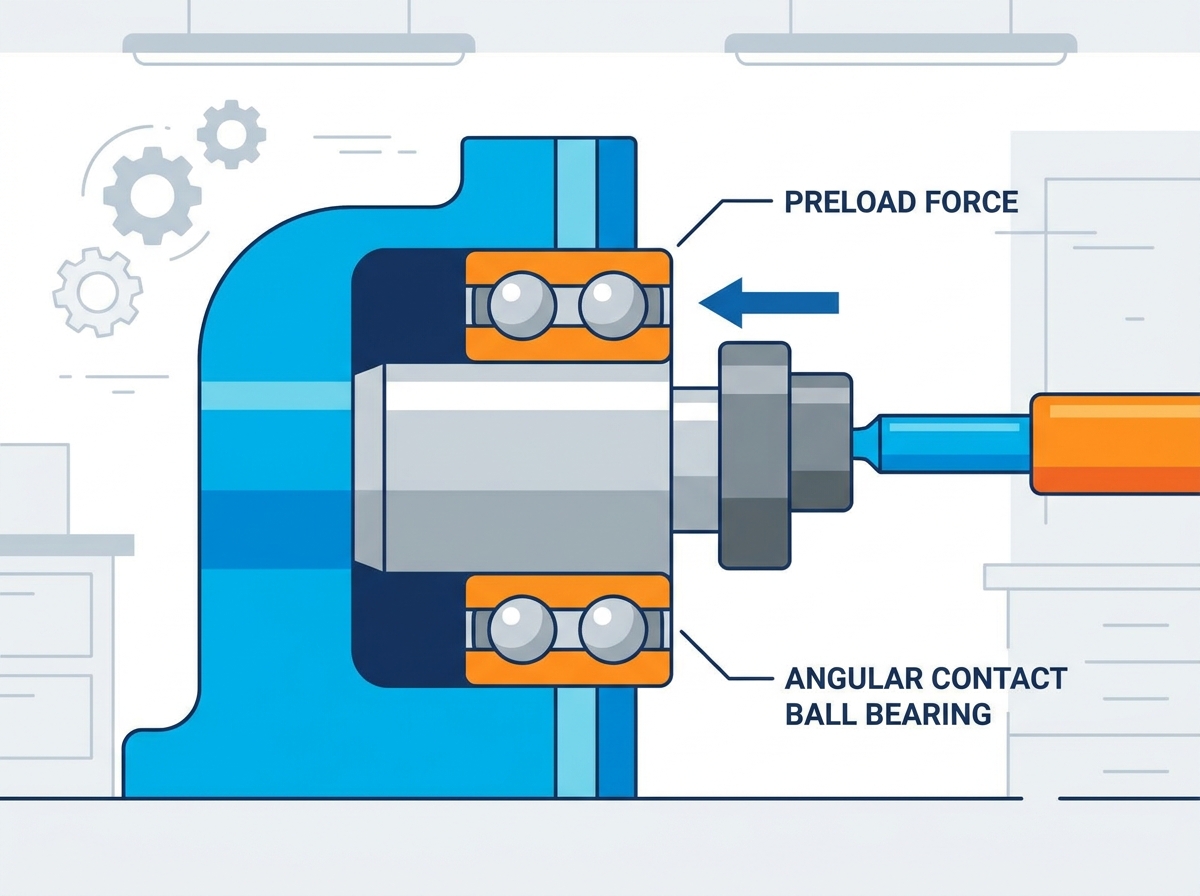
Universally matchable bearings rely on factory-preset flushness for paired mounting. When you clamp these bearings together, the offset between the inner and outer rings is eliminated, generating the exact specified preload. Alternatively, you can utilize precision-ground spacer rings between the bearings. Grinding the inner or outer spacer allows you to fine-tune the axial preload for custom applications. Employing coil or wave springs is another method. Spring preloading maintains a constant force, automatically compensating for thermal elongation during operation.
Analyzing how operating temperatures alter internal clearances is a mandatory engineering step. The rotating shaft typically runs hotter than the stationary housing. This thermal gradient causes the shaft to expand radially more than the housing. The inner ring expands, pushing the balls deeper into the outer raceway. This thermal expansion differential drastically increases the operating preload. Your initial mounting preload calculations must account for this phenomenon to prevent thermal lockup.
Step-by-Step Installation Procedure
- Environmental and Component Preparation: Establish a cleanroom-level workspace. Airborne dust acts as a lapping compound inside precision bearings. Thoroughly degrease the shaft and housing using industrial solvents. Deburr keyways and edges to prevent metal shavings from entering the assembly zone. Inspect all mounting surfaces for microscopic scoring or fretting wear from previous installations. Any surface irregularity will transfer directly through the bearing rings, distorting the raceways.
- Selecting the Right Installation Tooling: Evaluate and select the correct tooling to determine the mechanical success of the fit. Use mechanical presses, hydraulic tools, or induction heaters. Restrict the use of hammers, brass drifts, or punches entirely. Striking a bearing introduces localized impact risks. Even light taps can cause the balls to dent the raceways, a condition known as true brinelling. Always utilize tools that apply smooth, continuous, and evenly distributed force.
- Mounting the First Bearing: Orient the first bearing relative to the primary thrust direction based on your DB, DF, or DT requirement. For shaft installations requiring an interference fit, use an installation sleeve that contacts only the inner ring face. Apply a smooth, constant axial force using your press. For housing installations with an interference fit, the sleeve must contact only the outer ring face. Ensure the bearing is pressed firmly against the shaft shoulder. Validate flush seating by attempting to insert a 0.01mm feeler gauge between the inner ring and the shoulder.
- Mounting the Second Bearing & Aligning Match Marks: Align the laser-etched "V-line" across both bearing outer diameters precisely. Repeat the pressing operation for the second bearing. You must ensure absolutely no axial forces are transmitted through the balls of either bearing during this step. Once seated, apply the designated precision locknut or end-cap clamp. Torque the locknut to the manufacturer's exact specification to lock the assembly into place and engage the built-in preload.
- Thermal Mounting (Alternative Hot-Mounting Method): Thermal mounting is highly recommended for shafts with heavy interference fits. Use a professional induction heater equipped with a temperature probe. Limit the heating temperature to strictly 110°C (230°F). Exceeding this limit compromises the metallurgical stability of the steel and damages polyamide cages. Implement demagnetization cycles immediately after heating. As the bearing cools, it will contract radially and axially. You must hold the bearing firmly against the shaft shoulder during the cooling phase to prevent "shrink-back" gaps.
Post-Installation Validation and Testing
Using dial indicators with 1 µm resolution is necessary to measure the radial and axial runout of the completed shaft assembly. Rotate the shaft slowly by hand. The runout values must fall within the tolerances specified by your engineering drawings. Excessive runout indicates that a bearing is seated crookedly, dirt is trapped against the shoulder, or the shaft itself is bent. You must tear down and inspect the assembly if runout exceeds acceptable limits.
Structuring a gradual speed ramp-up protocol is critical for grease-lubricated spindles. Never start a newly rebuilt spindle at maximum RPM. Operate the system at 25%, 50%, 75%, and finally 100% duty cycles. This run-in procedure channels and distributes the grease evenly away from the rolling elements. It prevents grease churning and establishes a stable operating temperature baseline. Monitor the housing temperature continuously during this phase.
Capturing baseline frequency spectrum data using Fast Fourier Transform (FFT) vibration analysis confirms mechanical integrity. Compare the vibration peaks against known bearing defect frequencies. A clean spectrum confirms the absence of installation-induced defects. High amplitude peaks at ball pass frequencies indicate brinelling, severe alignment errors, or excessive preload applied during the locknut tightening phase.
Common Installation Risks and Mitigation Strategies
Minor impacts during assembly permanently dent the raceways. This shock loading causes true brinelling. When the machine runs, the balls roll over these microscopic dents, leading to early micro-spalling and rapid failure. You mitigate this risk entirely by using continuous-force press tools or induction heaters. Never allow the bearing to drop, and never strike it with any hand tools.
The impact of airborne particulate matter on sub-micron oil films is devastating. A single particle of hard dirt can bridge the lubrication film, scoring the steel surfaces. You must ensure bearings are unboxed only when you are absolutely ready to mount them. Keep your hands clean, use lint-free cloths, and never use compressed air to spin a dry bearing.
Identifying the symptoms of a bearing pressed on at an angle is necessary for failure analysis. A misaligned bearing exhibits uneven raceway wear paths. It will cause an immediate and sharp increase in operating temperature. The cage pockets will experience severe wear as the balls accelerate and decelerate erratically. You prevent this by ensuring perfectly perpendicular seating against the shaft shoulder and using properly squared pressing sleeves.
Conclusion
- Conduct an immediate audit of current maintenance protocols to ensure clean-room standards are enforced during assembly.
- Verify the orientation and V-line alignment requirements for your machine spindles before pressing any components.
- Reference manufacturer engineering datasheets for exact fit tolerances and preload torque specifications prior to your next assembly cycle.
- Invest in dedicated bearing fitting tool kits and induction heaters with demagnetization capability to eliminate hammer-induced brinelling.
FAQ
Q: How do you visually tell the face from the back of an angular contact ball bearing?
A: Look at the outer ring shoulders. The thick shoulder is the back, which handles the heavy axial thrust loads. The thin shoulder is the front face. The bearing must be oriented so the axial load pushes the inner ring toward the thick outer shoulder.
Q: What are the laser-etched "V-lines" on the outside of matched bearing pairs, and how do you align them?
A: The V-line indicates the high point of radial runout and the correct stacking sequence. You must align the lines across the outer diameters so they form a continuous "V" pointing in the direction specified by the assembly drawing.
Q: Can you apply press force to the outer ring when installing a bearing onto a shaft?
A: No. Applying force to the outer ring when pressing onto a shaft transmits the load directly through the balls. This causes true brinelling and ruins the raceways instantly. Always press only on the inner ring for shaft installations.
Q: What happens to the assembly if an angular contact ball bearing is installed backwards?
A: The axial load will force the balls against the thin, non-thrust shoulder of the raceway. The balls will ride over the edge of the raceway, destroying the cage and causing immediate catastrophic bearing failure.
Q: How does the shaft shoulder fillet radius affect angular contact ball bearing seating?
A: The shaft fillet radius must be smaller than the bearing's corner chamfer dimension. If the fillet is too large, the bearing will hit the radius before contacting the flat shoulder, causing severe angular misalignment and runout.
Q: What is the difference between DB, DF, and DT bearing arrangements regarding stiffness and misalignment tolerance?
A: DB (Back-to-Back) provides maximum stiffness and moment load resistance. DF (Face-to-Face) offers less stiffness but tolerates minor shaft misalignment better. DT (Tandem) provides maximum axial load capacity in one direction but requires an opposing bearing.
Q: What causes an angular contact bearing to overheat immediately during the initial run-in phase?
A: Immediate overheating is typically caused by excessive preload, severe angular misalignment, or grease churning due to over-lubrication. Failing to execute a gradual speed ramp-up protocol to channel the grease will also cause rapid temperature spikes.

 English


