High-performance machinery frequently experiences premature failure when standard bearings are subjected to complex, simultaneous multi-directional forces. Engineers and procurement teams must balance the need for high-speed operation, extreme rigidity, and the ability to handle both radial and axial loads without increasing the footprint of the assembly. Standard radial bearings simply cannot withstand the continuous thrust loads generated by helical gears, centrifugal pumps, or high-speed milling spindles. The Angular Contact Ball Bearing serves as the engineered solution for these combined loads. By utilizing an asymmetric raceway design, these components transfer forces across a specific contact angle, allowing for simultaneous radial and axial load accommodation. This guide breaks down the mechanics, core benefits, configuration options, and implementation risks to inform technical purchasing decisions and ensure optimal equipment reliability.
- Combined Load Mastery: Angular contact ball bearings are specifically designed with asymmetric raceways to accommodate significant axial (thrust) and radial loads simultaneously.
- Contact Angle Dictates Performance: The specific contact angle (typically ranging from 15° to 40°) directly determines the ratio of axial to radial load capacity; higher angles support heavier axial loads at the expense of maximum speed.
- Configuration is Critical: Achieving optimal rigidity requires precise duplexing arrangements (Back-to-Back, Face-to-Face, or Tandem) and carefully calibrated preload.
- The Super Precision Advantage: For high-precision applications like machine tool spindles, utilizing super precision classes (ABEC 7/9) dramatically reduces runout, vibration, and thermal heat generation.
- Primary Applications: They are the industry standard for high-speed, high-precision environments, including machine tool spindles, gearboxes, and industrial pumps.
The Mechanics: What Is an Angular Contact Ball Bearing?
Structural Anatomy: Asymmetric Raceways and the "Cup and Cone" Principle
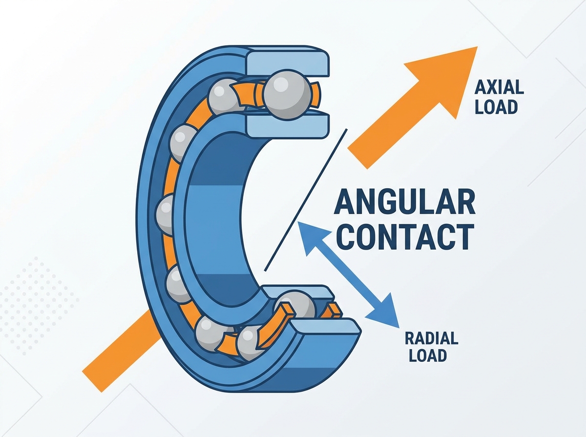
The internal geometry of an angular contact ball bearing features inner and outer ring raceways displaced relative to each other in the direction of the bearing axis. This displacement creates a specific line of action through the ball, transferring loads from one raceway to the other. Unlike standard deep groove bearings where the load passes radially through the center of the ball, the asymmetric design forces the load to travel at an angle. One shoulder of the inner ring and the opposite shoulder of the outer ring are raised, while the other shoulders are relieved. This geometry allows the bearing to support significant thrust loads in one direction.
Non-separable designs rely on this geometry to maintain structural integrity under load. The balls are typically inserted by expanding the outer ring thermally or by utilizing the relieved shoulder during assembly. Separable designs, such as magneto-type bearings, utilize a "cup and cone" anatomy. The outer ring (cup) can be removed from the inner ring and ball assembly (cone). This facilitates easier disassembly and mounting in specific configurations, particularly in small-scale precision instruments where press fits might damage the rolling elements during installation.
The Role of the Contact Angle
The contact angle defines the line of action mathematically and practically, dictating the load capacity ratio. It is the angle between the line connecting the points of contact of the ball and the raceways in the radial plane, along which the combined load is transmitted from one raceway to another, and a line perpendicular to the bearing axis. The selection of this angle is the most critical factor in specifying these bearings.
A 15° to 25° angle is optimized for high-speed applications with lower axial loads, such as precision spindles. The lower angle reduces the centrifugal force exerted by the balls on the outer raceway at high RPMs, minimizing heat generation and wear. Conversely, a 40° angle is optimized for heavy axial loads but features reduced speed thresholds, making it suitable for heavy-duty pumps and gearboxes where thrust forces dominate the load profile.
| Contact Angle | Primary Load Capacity | Speed Capability | Typical Applications |
| 15° (C) | High Radial, Low Axial | Extremely High | High-speed grinding spindles, precision routers |
| 25° (E) | Balanced Radial/Axial | High | Lathe spindles, moderate speed electric motors |
| 40° (B) | High Axial, Moderate Radial | Moderate | Centrifugal pumps, heavy-duty gearboxes, compressors |
Angular Contact vs. Radial (Deep Groove) Bearings: The Technical Trade-Offs
Load Distribution and Capability
Deep groove bearings feature symmetrical raceways designed primarily for radial loads with limited axial capacity. The deep, uninterrupted raceway grooves have a close osculation with the balls, enabling them to accommodate radial loads and some axial loads in both directions. However, when subjected to continuous, heavy thrust loads, the balls in a deep groove bearing will ride up on the edge of the raceway shoulder, leading to edge loading, excessive stress concentrations, and rapid spalling.
Angular contact bearings utilize asymmetric raceways to handle high unidirectional axial loads combined with radial loads efficiently. The raised shoulder provides a robust surface for the balls to transmit thrust forces without edge loading. This makes them vastly superior in applications where helical gears or fluid dynamics generate constant axial forces.
Speed, Rigidity, and Deflection
Under constant preload, angular contact bearings exhibit significantly lower deflection and minimal shaft runout under heavy operational stress compared to standard radial bearings. Preload removes all internal clearance, creating an elastically stiff system. When a cutting tool engages a workpiece, the resulting forces attempt to deflect the spindle shaft. A preloaded angular contact bearing resists this deflection much more effectively than a deep groove bearing, which typically operates with some internal clearance to accommodate thermal expansion.
This rigidity is crucial for maintaining accuracy in high-speed operations. Deep groove bearings can experience ball skidding and cage rattling under high acceleration or when radial loads are too light. The constant contact maintained by the preload in an angular contact setup prevents these kinematic issues, ensuring smooth, vibration-free rotation at high RPMs.
Decision Framework: When to Specify Which
Choosing between these two bearing types requires a systematic evaluation of the application's operating conditions. Use the following criteria to determine when an angular contact bearing is the necessary choice:
- Presence of Constant Thrust Loads: If the application generates continuous axial forces exceeding 25% of the radial load, standard deep groove bearings will likely fail prematurely.
- Requirement for Zero Internal Clearance: Applications demanding high positional accuracy, such as machine tool spindles or precision measuring equipment, require the zero-clearance environment provided by preloaded angular contact bearings.
- Necessity for High-Speed Precision: When operating at high dN values (bore diameter in mm multiplied by speed in RPM), the kinematic stability of a preloaded angular contact bearing prevents ball skidding and reduces heat generation compared to radial bearings operating with clearance.
- Need for High System Rigidity: If minimizing shaft deflection under varying loads is critical to the machine's function, the stiff elastic response of an angular contact arrangement is mandatory.
Key Benefits of Angular Contact Ball Bearings
Simultaneous Multi-Directional Load Capacity
These bearings handle combined loads within a single bearing envelope. This operational efficiency reduces the need for separate thrust and radial bearing assemblies, saving space and weight. In traditional setups, engineers might use a cylindrical roller bearing for radial loads and a separate thrust bearing for axial loads. This requires a longer shaft, a more complex housing, and intricate lubrication routing. An angular contact bearing consolidates these functions, allowing for more compact machine designs and reducing the overall component count.
Superior Rigidity and Vibration Dampening for Machine Tool Spindles
Angular contact bearings minimize shaft deflection and operational vibration. This directly improves manufacturing outcomes by enabling better surface finishes, tighter dimensional tolerances, and extended tool life in high-speed machining applications. When a milling cutter strikes a workpiece, it generates high-frequency vibrations. The stiff, preloaded interface of the bearing dampens these vibrations, preventing them from resonating through the spindle shaft and causing chatter marks on the machined surface.
Enhanced High-Speed Performance with Super Precision Engineering
The kinematic advantages of the contact angle and specialized cage designs reduce friction, lower operating temperatures, and allow for higher RPMs compared to tapered roller bearings. Tapered roller bearings can handle massive loads but suffer from high friction at the roller end and guide flange interface, limiting their speed. Angular contact balls have a much smaller contact area, generating less rolling resistance and heat.
Super precision grade bearings limit centrifugal ball sliding and thermal expansion at extreme rotational speeds. These bearings often utilize ceramic balls (hybrid bearings) which are lighter and stiffer than steel. The reduced mass of the ceramic balls lowers the centrifugal force exerted on the outer raceway, significantly reducing heat generation and allowing for speed increases of up to 30% over standard steel ball bearings.
Scalability and Customization via Duplexing
Engineers can stack these bearings to scale load capacity and rigidity based on specific application demands, offering significant design flexibility. By arranging multiple bearings in sets, the system can be tailored to handle heavy bi-directional thrust loads, extreme moment loads, or massive unidirectional forces. This modularity allows a single bearing series to be adapted for a wide variety of machines simply by changing the mounting arrangement and preload class.
Evaluation Dimensions: Selecting the Right Angular Contact Bearing
Row Configurations (Single, Double, Four-Point)
- Single-Row: Accommodates axial loads in one direction and requires pairing. These are the most common type and are almost always used in sets adjusted against each other to establish preload and handle reversing thrust loads.
- Double-Row: Functions as two single-row bearings back-to-back, handling bi-directional axial loads while saving space. They are supplied with a built-in internal clearance or preload and do not require external adjustment during installation.
- Four-Point Contact: Features a split inner or outer ring design to handle bi-directional thrust loads in a highly compact footprint, ideal for space-constrained applications. They are typically used purely as thrust bearings and are mounted with radial clearance in the housing to prevent them from taking radial loads.
Understanding Duplex Arrangements (DB, DF, DT)
When single-row bearings are used, they must be arranged correctly to achieve the desired performance characteristics. The choice of arrangement dictates the system's rigidity, load capacity, and tolerance for misalignment.
| Arrangement Code | Configuration Name | Load Direction | Moment Stiffness | Misalignment Tolerance |
| DB | Back-to-Back | Bi-directional | Very High | Low |
| DF | Face-to-Face | Bi-directional | Moderate | Moderate |
| DT | Tandem | Unidirectional (Heavy) | Low | Low |
Back-to-Back (DB): Provides high rigidity and handles overturning moments well due to widely spaced effective bearing centers. The lines of action diverge toward the bearing axis, creating a wide effective spread. This is the preferred arrangement for machine tool spindles and applications where shaft deflection must be minimized.
Face-to-Face (DF): Tolerates slight shaft misalignment better but offers lower moment stiffness. The lines of action converge toward the bearing axis, reducing the effective spread. This arrangement is often used when the housing is less rigid or when thermal expansion of the shaft might cause excessive preload in a DB arrangement.
Tandem (DT): Shares heavy axial loads in a single direction; requires a counter-bearing to handle reverse loads. The lines of action are parallel. This is used when the thrust load in one direction exceeds the capacity of a single bearing.
Cage Materials and Environmental Compliance
Cage selection depends on the application. Pressed steel serves general purposes and offers good strength at a low cost. Machined brass offers high reliability, heavy load capacity, and shock resistance, making it ideal for large pumps and compressors. Polyamide or PEEK cages are suited for high speed, low friction, and specific thermal limits. PEEK cages, in particular, offer excellent chemical resistance and can operate at higher temperatures than standard polyamide, making them suitable for demanding aerospace and high-speed spindle applications.
Tolerance and Precision Classes: Standard vs. Super Precision (ABEC/ISO)
Standard industrial tolerances (ABEC 1/3, ISO Normal/Class 6) suit general applications like electric motors and standard pumps. Super precision bearings (ABEC 7/9, ISO P4/P2) are required for high-speed, low-vibration machine tool spindles and aerospace applications to minimize runout. The higher precision classes ensure tighter control over bore and outside diameter tolerances, raceway geometry, and ball grading. This meticulous manufacturing reduces dynamic runout, ensuring the spindle rotates perfectly true, which is essential for achieving tight tolerances on machined parts.
Implementation Realities and Adoption Risks
The Critical Necessity of Preload
Angular contact bearings require a minimum axial load (preload) to function correctly, maintain ball contact, and prevent ball skidding. Preload is an internal force applied to the bearing set before external loads are introduced. It ensures that all balls share the load evenly and eliminates any radial or axial play in the system.
Incorrect preload carries severe risks. Over-preload causes excessive heat generation, thermal seizure, and premature wear. The increased friction rapidly degrades the lubricant, leading to metal-to-metal contact and catastrophic failure. Under-preload leads to axial play, noise, and insufficient rigidity. If the preload is too light, external loads can cause the balls on the unloaded side of the bearing to lose contact with the raceway, leading to skidding and rapid smearing of the raceway surface.
Installation Errors and Misalignment Tolerances
Proper installation is paramount. Backward installation in single-row configurations leads to immediate catastrophic failure when thrust is applied. If the bearing is mounted so the thrust load pushes the balls against the low, relieved shoulder, the balls will immediately ride over the edge, destroying the cage and the bearing. Installers must pay close attention to the thrust face markings on the bearing rings.
Strict alignment requirements, particularly for Back-to-Back (DB) arrangements, must be met, as misalignment severely impacts the bearing lifecycle. DB arrangements are highly rigid and unforgiving of angular misalignment between the shaft and housing. Any misalignment will induce heavy internal stresses, drastically reducing the fatigue life of the bearing. Precision machining of the shaft and housing seats is mandatory.
Lubrication Strategies for High-Speed Operation
As speed factors (dN values) increase, lubrication must transition from grease to oil-air or oil-mist systems to prevent thermal buildup and ensure reliable operation. Grease is suitable for moderate speeds, but at high RPMs, the churning of the grease generates excessive heat. Oil-air systems deliver a precise, metered amount of oil directly to the bearing contact zone, providing optimal lubrication while the compressed air cools the bearing and prevents the ingress of contaminants.
Conclusion
- Calculate exact radial and axial load requirements to determine the necessary contact angle and load capacity.
- Consult with a bearing application engineer to determine the optimal preload class (Light, Medium, or Heavy) based on the required rigidity and operating speed.
- Specify the correct duplex arrangement (DB, DF, or DT) to accommodate the direction of thrust loads and the required moment stiffness.
- Select the appropriate precision class (ABEC 7/9 for high-speed spindles) to ensure minimal runout and vibration.
- Request technical catalogs or CAD models from the manufacturer to ensure proper integration into the housing and shaft design.
FAQ
Q: Can angular contact ball bearings take radial loads?
A: Yes, they handle radial loads exceptionally well, provided there is a simultaneous axial load or proper preload applied to keep the balls seated securely against the raceways.
Q: What is the benefit of "Super Precision" angular contact bearings?
A: ABEC 7/9 ratings minimize dimensional runout, vibration, and friction. This precision is vital for high-speed machine tool spindles requiring high accuracy and low heat generation.
Q: What happens if an angular contact bearing is installed backward?
A: The balls will ride against the low shoulder of the asymmetric raceway, causing the bearing to separate under load. This leads to immediate loss of support and catastrophic mechanical failure.
Q: How do you determine the correct contact angle for an application?
A: Higher axial loads require higher angles, such as 40°. Higher speeds and the need for radial rigidity require lower angles, such as 15° or 25°.
Q: What is the difference between cup-and-cone (tapered roller) and angular contact ball bearings?
A: Tapered rollers handle significantly heavier shock and radial loads but at lower operating speeds. Angular contact balls handle higher speeds with greater precision and lower heat generation.
Q: Why do angular contact bearings require preload?
A: Preload maintains constant contact between the balls and raceways. This prevents ball skidding, minimizes dynamic runout, and ensures overall system rigidity.
Q: Can I replace a deep groove ball bearing with an angular contact bearing?
A: While dimensionally similar in some series, the application must have an axial load component or be paired and preloaded to function correctly. Otherwise, the bearing will fail prematurely.

 English


