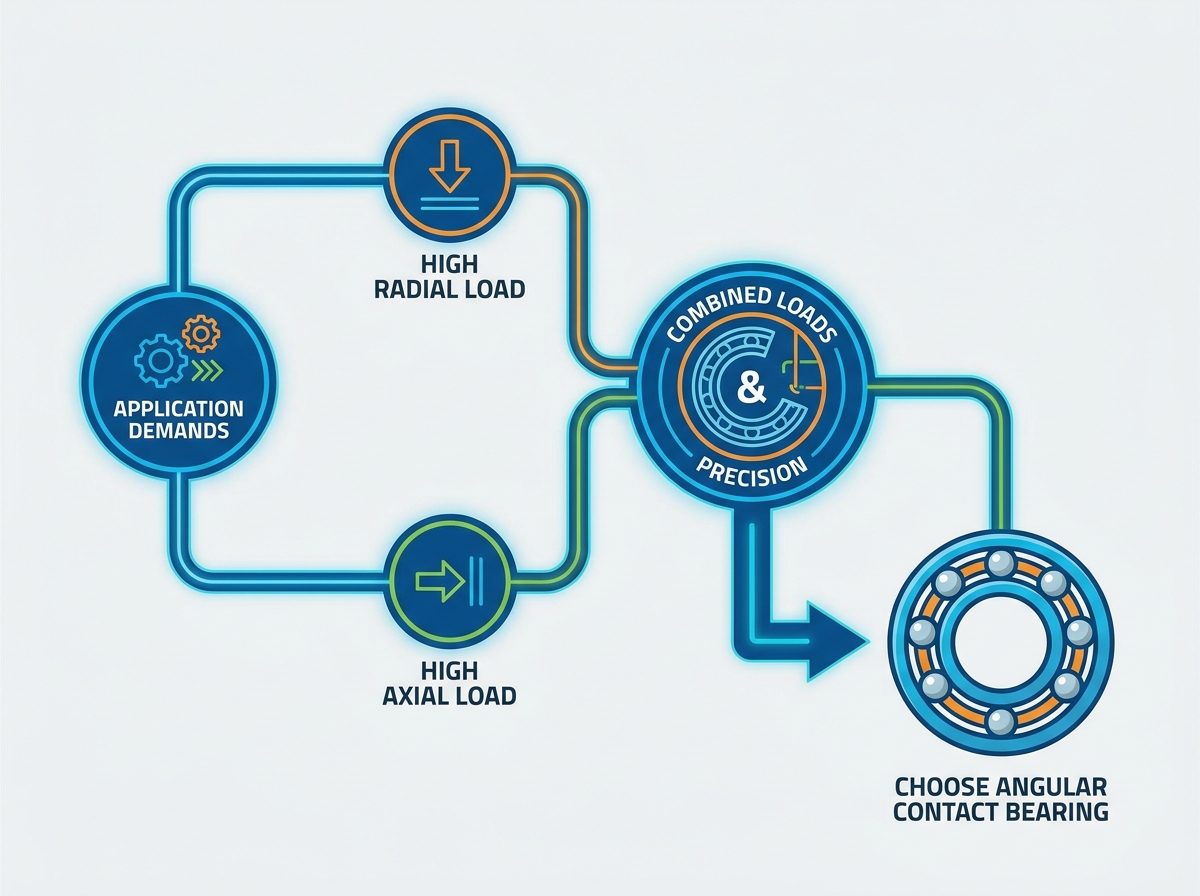
Managing simultaneous high-speed rotation and combined loads without compromising system rigidity presents a strict engineering challenge. When designing rotating equipment, engineers must evaluate the exact vector forces acting on the shaft to select the correct components. Defaulting to standard deep groove radial bearings (the 6000 series) in high-axial load or high-precision environments is a common misapplication. This error leads directly to premature fatigue failure, excessive vibration, and costly machine downtime. Standard radial bearings simply lack the internal geometry to handle continuous thrust.
The engineered solution for these combined load scenarios is the 7000 series Angular Contact Ball Bearing. Transitioning to this asymmetric design requires a strict evaluation of contact angles, arrangement configurations, and preload requirements. Proper specification ensures mechanical reliability, maintains shaft alignment under heavy cutting or pumping loads, and maximizes the operational lifespan of the machinery.
Key Takeaways
- Load Handling: Angular contact ball bearings are mandatory when an application requires the simultaneous support of heavy radial and unidirectional axial loads.
- Speed and Precision: Their continuous, non-stop ball-to-ring contact design allows for significantly higher RPM ratings and tighter tolerances compared to standard radial bearings.
- Configuration Dependency: Single bearings only support axial loads in one direction; successful implementation usually requires paired arrangements (Back-to-Back, Face-to-Face, or Tandem) to manage bidirectional forces and moment loads.
- Implementation Risk: Improper preload, misalignment, or failure to account for thermal expansion can lead to rapid thermal runaway and catastrophic bearing failure.
The Mechanics of an Angular Contact Ball Bearing
How Contact Angle Dictates Load Capacity
The contact angle is defined as the angle between the line connecting the points of contact of the ball and the raceways in the radial plane, along which the load is transmitted from one raceway to another. This angle typically ranges from 15° to 40° and directly correlates to load distribution. A larger contact angle provides higher axial load capacity. Conversely, a smaller contact angle maximizes speed capabilities by reducing the centrifugal sliding friction of the balls against the outer raceway.
Engineers face a distinct trade-off during specification. Bearings with a 40° angle, often designated with a 'B' suffix, handle heavy thrust but have lower maximum speed limits. Those with a 15° angle, carrying a 'C' suffix, excel at high speeds but sacrifice axial load capacity. A reliable engineering heuristic matches angle degrees to application types: use 15° for high-speed CNC spindles, 25° for precision ball screws, and 40° for heavy-duty vertical pumps. Selecting the wrong angle results in either rapid overheating at high RPMs or immediate brinelling under heavy thrust.
Radial vs. Angular Contact Bearings: The Core Distinction
Internal geometries separate these two bearing types. An angular contact bearing features an asymmetric raceway. One shoulder of the inner or outer ring is relieved, allowing for a higher complement of balls and establishing the specific contact angle. A standard radial bearing utilizes a symmetric deep groove design intended primarily for radial forces. The asymmetric design allows the bearing to accept thrust loads that would otherwise destroy a standard bearing.
When subjected to continuous axial thrust, radial bearings experience severe stress concentrations on the raceway edges. The balls ride up on the shallow shoulder of the deep groove, leading to rapid ball spalling, cage fracture, and eventual catastrophic seizure. Upgrading to an asymmetric design provides the technical justification needed to handle these continuous thrust loads safely, keeping the balls firmly seated in the deep pocket of the raceway.
Structural Formats: Cup-and-Cone vs. Sealed Cartridge Designs
Mechanical differences exist between traditional adjustable "cup-and-cone" designs and high-precision integrated cartridge bearings. Cup-and-cone formats, common in automotive hubs and bicycle applications, allow users to manually adjust internal clearance during installation. However, they are susceptible to contamination and rely heavily on technician skill to set the correct preload. Overtightening a cup-and-cone bearing leads to immediate failure.
Cartridge bearings provide superior contamination exclusion through integrated seals or shields. They feature factory-set internal clearances, eliminating installation guesswork. The trade-off requires tighter shaft and housing tolerances to prevent housing distortion from affecting the bearing's internal geometry. Machining a housing out of round will compress the thin outer ring of a cartridge bearing, creating tight spots that cause localized overheating and premature wear.
Standard Nomenclature: Decoding the 7000 Series vs. 6000 Series
Identifying bearings on engineering drawings requires understanding standard nomenclature. The 6000 series represents deep groove radial ball bearings. The 7000 series signifies standard single-row angular contact ball bearings. Recognizing this distinction prevents critical procurement errors on the assembly floor.
Common suffix codes further define the bearing's capabilities. Suffixes like C, AC, and B denote contact angles of 15°, 25°, and 40°, respectively. Paired arrangements utilize suffixes such as DB (Back-to-Back), DF (Face-to-Face), and DT (Tandem). Accurate specification relies on decoding these alphanumeric strings correctly. For example, a 7210-B-TVP indicates a 50mm bore angular contact bearing with a 40-degree angle and a polyamide cage.
Primary Evaluation Criteria for Angular Contact Ball Bearings
Load Direction, Magnitude, and Combined Forces
Establishing a mathematical framework is necessary for calculating the ratio of axial load to radial load in the system. Engineers must determine the limiting thrust factor, known as the e parameter. This parameter represents the critical threshold at which a combined load necessitates a shift from standard radial bearings to angular contact designs. You must calculate the equivalent dynamic bearing load (P) using the formula P = XFr + YFa, where X and Y are radial and axial load factors derived from the bearing catalog.
When the ratio of axial to radial load exceeds the e value, the axial forces dominate the contact mechanics. At this point, standard deep groove bearings will fail prematurely, mandating a specialized solution. Ignoring these calculations and guessing the load distribution usually results in undersized bearings that fail within the first few hundred hours of operation.
Operating Speeds and Kinematic Stability
These bearings excel at high RPMs due to reduced ball skidding and continuous raceway contact. Optimized phenolic or polyamide cage designs further enhance kinematic stability by reducing friction and wear at high velocities. Brass cages are sometimes used for high-temperature applications, but they add mass and reduce the maximum speed rating compared to lightweight polymer alternatives.
Centrifugal forces impact the balls at extreme speeds. The contact angle shifts dynamically under operation, altering the load zone and affecting heat generation. Engineers must account for these dynamic shifts when calculating thermal limits and lubrication intervals. At ultra-high speeds, the balls try to ride outward, changing the inner and outer contact angles. This kinematic shift requires specialized preload adjustments to prevent the balls from skidding and scoring the raceway.
System Rigidity, Tolerances, and Precision Classes
Precision classes, such as ABEC 5, 7, 9 or ISO Class 5, 4, 2, play a vital role in minimizing runout and rotational deviation. Higher precision classes ensure tighter dimensional controls on the bore, outer diameter, and raceway runout. Standard ABEC 1 bearings are entirely unsuitable for machine tool spindles or high-speed aerospace applications.
In high-tolerance environments, these bearings minimize shaft deflection. They maintain strict rotational accuracy, which is critical for applications like machine tool spindles where microscopic deviations ruin surface finishes. Specifying an ABEC 7 bearing requires matching shaft and housing tolerances; pressing a high-precision bearing onto a poorly machined shaft negates all the benefits of the expensive bearing.
Space Envelope Constraints: Bore, Outer Diameter, and Width Series
Boundary dimensions restrict or enable specific bearing selections. ISO Dimension Series 18, 19, 10, 02, and 03 dictate the cross-sectional profile of the bearing for a given bore size. A series 10 bearing has a much smaller cross-section than a series 03 bearing with the same bore diameter.
Thin-section variants maximize the bore diameter for hollow shafts, saving weight and space. Heavy-duty series maximize cross-sectional width and ball size for extreme load handling. The space envelope dictates which series fits the mechanical assembly. When retrofitting equipment, you are often locked into a specific dimension series and must optimize the internal geometry and cage design to increase load capacity within the existing footprint.
Selecting the Right Bearing Arrangement Configuration
Back-to-Back (DB / O-Arrangement) Configuration
The Back-to-Back setup features load lines diverging toward the bearing axis, forming an "O" shape. This configuration provides the widest effective bearing spread. The inner rings are clamped together, and the outer rings are separated by a spacer or clamped in the housing.
It is the optimal choice for high rigidity and handling heavy overturning moment loads. The wide spread resists shaft deflection better than any other paired arrangement. This is the default configuration for cantilevered loads, such as overhung impellers or pulleys, where moment forces attempt to bend the shaft during operation.
Face-to-Face (DF / X-Arrangement) Configuration
The Face-to-Face setup features load lines converging toward the bearing axis, forming an "X" shape. The effective center distance is shorter than the DB arrangement. The outer rings are clamped together, and the inner rings are separated.
This is the ideal solution for applications requiring slight misalignment tolerance or where shaft expansion must be accommodated. However, it offers lower moment load capacity compared to the DB configuration. DF arrangements are commonly used in gearboxes where the housing might distort slightly under heavy torque, allowing the bearings to articulate without binding.
Tandem (DT) Configuration
The Tandem setup features parallel load lines. Both bearings face the same direction, sharing the axial load equally. This requires precise factory matching to ensure both bearings carry the exact same amount of load.
It maximizes unidirectional axial load capacity by distributing the thrust across multiple bearings. This setup strictly requires a counter-opposed bearing or set to handle any reverse axial forces. If a DT pair is subjected to reverse thrust, the bearings will immediately unseat and fail. They are often used in vertical pumps where the weight of the fluid and the impeller creates a massive, constant downward force.
| Configuration | Load Line Shape | Moment Load Capacity | Primary Use Case |
| Back-to-Back (DB) | Diverging ("O") | High | Maximum rigidity, heavy moment loads, cantilevered shafts |
| Face-to-Face (DF) | Converging ("X") | Low | Misalignment tolerance, thermal expansion, gearboxes |
| Tandem (DT) | Parallel | None (Unidirectional) | Extreme unidirectional axial loads, vertical pumps |
Step-by-Step Decision Protocol for Specifying an Angular Contact Ball Bearing
- Quantify Dynamic and Static Combined Loads: Calculate the radial and axial vector forces under worst-case operating scenarios. Accurate load profiling prevents undersizing the bearing. Include shock loads and startup torque in your calculations.
- Determine Required Speed Rating (dn Value): Multiply the bore diameter in millimeters by the operating speed in RPM. Verify if the resulting dn limits require ceramic hybrid balls or specialized cage materials. Standard steel balls usually max out around a dn value of 1,000,000.
- Select the Optimal Contact Angle and Precision Class: Match the application's speed and load balance with the appropriate angle. Use 15° for speed-focused designs and 40° for thrust-heavy applications. Select the target ABEC or ISO rating based on runout requirements.
- Establish Configuration and Preload Level: Choose the physical arrangement (DB, DF, or DT) based on rigidity needs. Assign a light, medium, or heavy preload to eliminate internal clearance. Heavy preload increases rigidity but generates significantly more heat.
- Define Sealing, Shielding, and Lubrication Suffixes: Choose between open, shielded (Z), or sealed (2RS) variants. This decision depends on environmental contamination risks and lubrication service life targets. Open bearings require external lubrication systems.
Implementation Realities, Risks, and Trade-Offs
Preload Requirements and Thermal Runaway Risks
Preload eliminates internal clearance, increases rigidity, and prevents ball skidding. It is categorized into light, medium, and heavy classes. Factory-matched sets are ground to provide a specific preload when clamped together with a specified locknut torque.
Excessive preload combined with thermal expansion causes extreme danger. It can trigger thermal runaway and rapid bearing seizure. Engineers must calculate thermal gradients between the rotating shaft and stationary housing to mitigate this risk. If the shaft heats up faster than the housing, it expands radially, increasing the internal preload. If the initial preload was already heavy, this thermal expansion pushes the bearing into a locked state, destroying it in minutes.
Lubrication and Sealing Constraints: Open vs. Shielded vs. Sealed
Sealed bearings have lower limit speeds due to contact seal friction. The rubber lip dragging on the inner ring generates heat. Open bearings handle higher speeds but require external lubrication systems, such as oil baths or circulating oil.
The asymmetric design complicates lubrication retention. Selecting the correct grease fill volume, typically 30% for high-speed applications, is critical. Overpacking the bearing with grease causes churning, which generates massive amounts of heat and degrades the lubricant. Ultra-high-speed spindles often require oil-air mist systems that deliver microscopic droplets of oil directly to the raceway, providing lubrication and cooling simultaneously.
Cost-to-Performance Ratio and Over-Engineering
These bearings carry higher procurement, mounting tolerance, and installation costs compared to standard deep groove bearings. Over-engineering wastes resources. Specifying an ABEC 7 matched set for a low-speed conveyor roller is a massive waste of capital.
Evaluate if the application truly requires angular contact precision. Sometimes, a standard deep groove bearing with a larger clearance class, such as C3, suffices for moderate axial loads. The C3 clearance allows the deep groove bearing to accept a slight contact angle under thrust, which is often enough for fractional horsepower motors or light-duty fans.
Common Applications and Success Criteria
High-Speed Machine Tool Spindles
Success requires extreme rotational accuracy and low vibration. Management of dynamic cutting forces relies on matched precision DB sets. Spindles often use ceramic hybrid bearings with 15-degree contact angles to achieve speeds exceeding 20,000 RPM without overheating.
Industrial Pumps and Compressors
Success involves handling continuous, heavy axial thrust generated by impellers and fluid dynamics. Maintaining seal integrity typically utilizes 40° contact angle bearings. API 610 pumps frequently specify back-to-back 40-degree bearings to handle the severe thrust loads generated by high-pressure fluid transfer.
Automotive and Aerospace Gearboxes
Success demands high power density and a compact footprint. Reliability under fluctuating, bidirectional combined loads requires robust DF arrangements. Helical gears generate significant axial thrust that reverses direction during deceleration; angular contact pairs absorb these reversing loads while maintaining gear mesh alignment.
Conclusion
- Review your application's load profile to confirm that simultaneous radial and axial forces are present before specifying an angular contact design.
- Calculate the exact dn value of your shaft to determine if standard steel balls are sufficient or if ceramic hybrid components are required.
- Select the appropriate contact angle (15°, 25°, or 40°) based strictly on the ratio of speed to axial load capacity.
- Specify the correct paired arrangement (DB, DF, or DT) to handle moment loads and shaft deflection in your specific housing design.
- Consult manufacturer load-rating charts and thermal expansion models to verify that your chosen preload class will not result in thermal runaway.
FAQ
Q: What is the main difference between deep groove and angular contact ball bearings?
A: Deep groove bearings (6000 series) have symmetric raceways designed primarily for radial loads. Angular contact bearings (7000 series) feature asymmetric raceways with specific contact angles, allowing them to handle continuous, heavy axial loads simultaneously with radial loads.
Q: Can a single angular contact ball bearing take radial loads?
A: Yes, it can take radial loads, but it must be subjected to an axial force simultaneously. This axial force, either externally applied or generated by a paired bearing, is necessary to keep the balls properly seated against the asymmetric raceway.
Q: How do I choose between a 15-degree and a 40-degree contact angle?
A: Choose a 15-degree angle for applications requiring very high speeds but lower axial loads, such as CNC spindles. Select a 40-degree angle for applications with heavy axial thrust but lower operating speeds, like industrial pumps.
Q: What does a DB arrangement mean?
A: DB stands for Back-to-Back arrangement. The load lines diverge toward the bearing axis, forming an "O" shape. It provides maximum system rigidity and is excellent for handling heavy overturning moment loads.
Q: Why do angular contact bearings fail prematurely?
A: Premature failure usually stems from improper preload, misalignment, or inadequate lubrication. Excessive preload combined with thermal expansion is a common cause of thermal runaway and rapid seizure.
Q: Are sealed angular contact bearings suitable for high-speed spindles?
A: Generally, no. Contact seals generate friction and heat, significantly lowering the maximum speed rating. High-speed spindles typically use open bearings with specialized oil-air mist lubrication systems.

 English


