Bearings form the mechanical foundation of power transmission systems. Premature bearing failure stands as the leading cause of catastrophic gearbox breakdowns and unplanned downtime across industrial sectors. When a bearing fails, gears misalign, shafts deflect, and the entire transmission system grinds to a halt. The complexity of specifying a bearing for Gearbox environments lies in managing extreme torque, fluctuating loads, and thermal expansion while maintaining precise mechanical integrity.
Engineers must evaluate load profiles, speed limitations, and environmental factors to specify the exact bearing for long-term gearbox reliability. This requires a systematic framework that balances dynamic capacities against real-world operating constraints. By analyzing shaft kinematics, lubrication requirements, and precision fits, you can select bearings that maximize uptime and prevent costly failures. We rely on field-tested engineering principles to ensure every component withstands the harsh realities of industrial operation.
- Load and Speed Dictate the Baseline: Selecting the correct bearing requires balancing dynamic/static load capacities against rotational speed limits; roller bearings handle heavy loads, while ball bearings excel at high speeds.
- L10 Life and Safety Factors are Key: Theoretical fatigue life calculations must be adjusted for real-world operating conditions, including lubrication quality, contamination, and static safety factors ($S_0$).
- Precision and Fits Prevent Failure: Proper shaft and housing tolerances are non-negotiable; incorrect interference fits lead to internal clearance loss and rapid thermal degradation.
- Total Cost of Ownership (TCO) Outweighs Initial Cost: Investing in application-specific materials, advanced cage designs, and proper sealing drastically reduces maintenance intervals and replacement costs.
Evaluating Bearing Selection: The 8-Step Engineering Framework
Step 1: Analyze Operating Conditions and Boundaries
The first step in selecting a bearing involves defining the gearbox type. Planetary, helical, spur, and bevel gearboxes each impose unique mechanical demands on their internal components. You must establish the baseline operational inputs, including input power, output torque, and duty cycles. Field experience shows that neglecting peak torque loads during startup often leads to early raceway fatigue.
External parameters heavily influence bearing performance. Assess the environmental temperature, ambient humidity, and expected vibration profile. Mounting orientation also plays a major role. Vertical shafts require different bearing arrangements and lubrication strategies compared to horizontal configurations to prevent oil starvation at the upper bearing positions.
Step 2: Determine Load Profiles (Radial, Axial, and Combined)
Dynamic load forces act continuously on gearbox shafts during operation. Gear meshing generates tangential, radial, and axial thrust forces, particularly in helical and bevel gear designs. Engineers calculate these forces accurately to determine the required dynamic load rating. You must map out the force vectors for every gear stage.
Static loads and peak shock loads occur during startup, braking, or emergency shutdown conditions. The static safety factor ($S_0$) prevents permanent plastic deformation, known as brinelling, on the raceways. When radial and axial forces act simultaneously on a single bearing location, calculate the equivalent dynamic bearing load to ensure the selected component handles the combined stresses without premature flaking.
Step 3: Assess Rotational Speed (RPM) and Kinematic Limits
Gearbox shafts operate at vastly different speeds. The high-speed input shaft typically handles low torque and high RPM, while the low-speed output shaft manages high torque at low RPM. These distinct kinematic profiles require different bearing types to optimize performance and prevent overheating.
Evaluate thermal reference speed limits against mechanical limiting speeds. Rolling element mass, centrifugal forces, and contact areas generate friction during operation. This friction limits the maximum safe operating RPM for specific bearing geometries. Exceeding these limits causes rapid lubricant degradation and thermal runaway.
Step 4: Map Bearing Types to Shaft Requirements
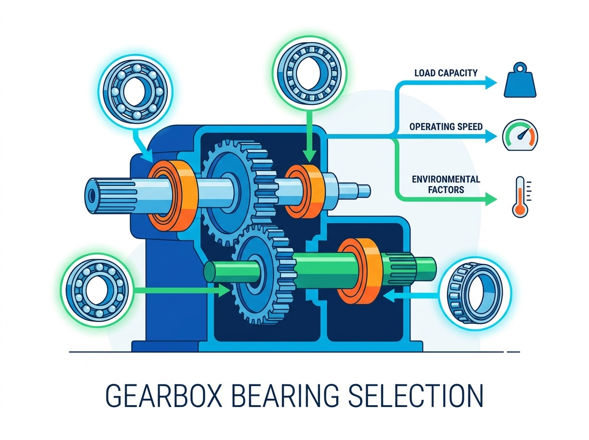
Matching bearing kinematics to specific gearbox stages ensures optimal power transmission. Cylindrical roller bearings often support input shafts due to their high-speed capabilities. Tapered roller bearings excel on output shafts where heavy combined loads dominate the mechanical environment.
Bearing arrangements must accommodate thermal expansion of the shaft. Engineers typically employ fixed-floating, adjusted, or floating bearing systems. A fixed bearing locates the shaft axially, while a floating bearing allows axial displacement to prevent internal stress buildup as temperatures rise during continuous operation.
| Gearbox Stage | Typical Load Profile | Recommended Bearing Type | Primary Engineering Focus |
| Input Shaft | High Speed, Low Radial Load, Minimal Axial | Cylindrical Roller / Deep Groove Ball | Friction reduction, thermal speed limits |
| Intermediate Shaft | Medium Speed, Moderate Combined Loads | Tapered Roller / Angular Contact | Precise preload setting, gear mesh alignment |
| Output Shaft | Low Speed, High Torque, Heavy Combined Loads | Spherical Roller / Heavy-Duty Tapered | Static safety factor, misalignment tolerance |
Step 5: Specify Lubrication and Sealing Systems
Lubrication minimizes friction and prevents metal-to-metal contact. Splash or oil bath lubrication suits many standard gearboxes. High-speed or heavy-duty applications often require forced-circulation oil systems with integrated oil coolers to maintain thermal stability and flush out wear particles.
Viscosity index requirements depend on expected operating temperatures. The lubricant must maintain an adequate film thickness, measured by the lambda ratio ($\Lambda$), to separate the rolling elements from the raceways. Sealing configurations, such as radial shaft seals, labyrinth seals, or taconite seals, prevent oil leakage and exclude external contaminants like dust and moisture.
Step 6: Define Operating Temperature and Thermal Balance
Calculating the thermal equilibrium of the gearbox ensures long-term reliability. Engineers balance the heat generated by bearings and gears against the heat dissipated through the housing and cooling systems. You must account for ambient temperature spikes in industrial environments.
Establishing limits for high-temperature operations prevents premature lubricant aging and material softening. Excessive heat degrades oil viscosity, leading to boundary lubrication and accelerated wear. Maintaining thermal balance ensures the bearing operates within its designed temperature range, preserving the metallurgical integrity of the raceways.
Step 7: Specify Tolerances, Fits, and Internal Clearance
Selecting the correct ISO shaft and housing fit classes (e.g., m5, k6, JS7) prevents creep or fretting corrosion between the bearing rings and the mating components. The fit must be tight enough to prevent rotation but not so tight that it eliminates internal clearance. Field mechanics frequently encounter seized bearings caused by overly aggressive interference fits.
Determining the correct radial and axial internal clearance (e.g., CN, C3, C4) ensures sufficient operating clearance after thermal stabilization. As the bearing heats up during operation, the inner ring expands more than the outer ring, reducing the internal clearance. Selecting the appropriate initial clearance prevents catastrophic overheating and seizure.
Step 8: Plan for Installation, Monitoring, and Dismounting
Incorporating features for ease of maintenance simplifies assembly and reduces the risk of damage. Mounting chamfers and puller grooves facilitate safe installation and removal during rebuilds. Designing the housing with maintenance in mind saves hours of labor during scheduled turnarounds.
Selecting condition-monitoring access points allows maintenance teams to track bearing health. Strategically placed sensors for vibration analysis and temperature probes provide real-time data. This enables predictive maintenance and prevents unexpected failures that halt production lines.
Deep-Dive: Evaluating Bearing Types for Gearbox Applications
Tapered Roller Bearings: Heavy-Duty and Combined Loads
The geometry of tapered rollers allows them to handle massive simultaneous radial and axial loads. The angled raceways direct load forces toward the central axis, providing exceptional stability under heavy stress. We frequently specify these for high-torque output stages where gear separation forces are extreme.
These bearings commonly operate in back-to-back (DB) or face-to-face (DF) arrangements on intermediate and output shafts in heavy industrial gearboxes. Precision mounting procedures are required to set exact end-play or preload during installation. Mechanics must use dial indicators to verify the axial clearance, ensuring optimal load distribution and shaft rigidity.
Cylindrical Roller Bearings: High Radial Loads and Rigidity
Cylindrical roller bearings feature a line-contact design that provides exceptional radial stiffness and load capacity. This geometry distributes loads over a larger area compared to point-contact ball bearings, making them highly resistant to radial deflection under heavy gear meshing forces.
They fit perfectly on high-speed input shafts where axial loads are minimal or managed by a separate thrust bearing. Variations such as NU, NJ, and NUP designs offer different capabilities for accommodating axial shaft displacement due to thermal expansion. The NU design, for instance, allows the shaft to float freely within the housing, eliminating thermally induced axial stresses.
Spherical Roller Bearings: Misalignment Tolerance
Spherical roller bearings possess self-aligning capabilities, tolerating up to 1.5 to 2 degrees of misalignment. The spherical outer ring raceway allows the inner ring and roller assembly to pivot. This compensates for shaft deflection or housing deformation under heavy loads.
They dominate heavy-duty, low-speed gearbox applications, such as mining equipment, conveyors, and wind turbine main gearboxes. Engineers balance their high load capacity and misalignment tolerance against lower maximum speed ratings. The sliding friction inherent in their design generates more heat, requiring careful lubrication planning.
Angular Contact and Deep Groove Ball Bearings
Angular contact ball bearings feature a contact angle that allows them to support significant axial loads in one direction. This makes them ideal for high-speed helical gear shafts where thrust forces are prominent. Mounting them in pairs (tandem, back-to-back, or face-to-face) provides rigid shaft support in both directions.
Deep groove ball bearings offer versatility for light-to-moderate radial loads and high-speed input shafts. Their low friction coefficient and minimal maintenance requirements make them a reliable choice for less demanding gearbox stages. They run cooler than roller bearings, extending lubricant life in high-RPM applications.
Technical Evaluation Dimensions: Features to Outcomes
Metallurgy and Component-Level Material Quality
Bearing metallurgy directly impacts fatigue life and shock resistance. Standard through-hardened carbon chromium steel (e.g., 100Cr6 / 52100) provides excellent wear resistance for general applications. Case-carburized steel (e.g., 18CrNiMo7-6) offers a tough core and hard surface. We use case-carburized variants to absorb high shock loads without cracking the rings.
Integrating silicon nitride ($Si_3N_4$) ceramic rolling elements creates hybrid bearings. These prevent electrical erosion in wind turbines or electric vehicle gearboxes while operating at lower temperatures. Material cleanliness, achieved through vacuum-arc remelted (VAR) or electroslag remelted (ESR) steels, reduces non-metallic inclusions. Surface treatments like black oxide coatings or manganese phosphating prevent adhesive wear, fretting corrosion, and micro-pitting during the critical run-in phase.
Fatigue Life and the Modern L10 Calculation
The standard $L_{10}$ and modified $L_{10m}$ ISO 281 calculations predict theoretical fatigue life based on load and speed. These formulas provide a baseline for comparing different bearing options. You must run these calculations for every bearing position in the gearbox to ensure the system meets the required design life.
The life modification factor ($a_{ISO}$) adjusts the theoretical life to account for real-world conditions. It incorporates lubrication film thickness ($\kappa$), the contamination factor ($e_c$), and the fatigue limit load ($C_u$). A high contamination factor drastically reduces the calculated life, highlighting the importance of robust sealing systems in dirty environments.
Cage Design and Material
Cage design influences bearing speed limits, friction, and durability. Stamped steel cages are standard and lightweight, suitable for general-purpose applications. Machined brass cages offer superior performance under vibration, shock loads, and high acceleration. We specify brass cages for heavy industrial gearboxes subjected to continuous impact loading.
Polyamide or polymer cages (e.g., PA66, PEEK) provide lower friction and emergency running capabilities. Engineers must carefully evaluate their strict temperature limits and compatibility with certain extreme pressure (EP) lubricant additives before specifying them. High operating temperatures quickly degrade polymer cages, leading to catastrophic bearing failure.
Overall Value and Conceptual Trade-offs
Speed vs. Load Capacity
Engineers face an inherent trade-off between speed and load capacity. Bearings with high load capacities, such as large rollers or full complement designs, inherently generate more friction and have lower speed limits. You cannot maximize both variables simultaneously.
Prioritizing one over the other depends on the specific gearbox stage. Input shafts generally require high-speed capabilities with lower load ratings. Output shafts demand maximum load capacity at lower speeds. Selecting the right balance ensures the gearbox operates efficiently without overheating or suffering premature fatigue.
Standard vs. Custom-Engineered Solutions
Off-the-shelf catalog bearings are sufficient for many standard gearbox applications, offering reliable and readily available solutions. However, OEM gearbox designs often push mechanical limits beyond standard catalog specifications.
When standard options fall short, custom profiles, special internal clearances, or proprietary coatings become necessary. Engineers evaluate whether the performance gains of custom-engineered solutions justify the extended lead times. In high-stakes applications like aerospace or heavy mining, custom bearings provide the necessary reliability margin.
Implementation Risks and Mitigation Strategies
Shaft and Housing Fits (Clearance vs. Interference)
Incorrect tolerance stack-ups pose significant risks. A fit that is too loose causes fretting corrosion and shaft wear. A fit that is too tight eliminates internal clearance and causes catastrophic overheating. Machinists must adhere strictly to the specified ISO tolerance bands.
Selecting proper transition or interference fits depends on the load direction. Rotating loads require tighter interference fits to prevent creep. Stationary loads can utilize looser transition fits to facilitate assembly and accommodate thermal expansion. Always verify the shaft and housing dimensions with calibrated micrometers before installation.
Lubrication Failures and Sealing Mechanisms
Over 50% of bearing failures are lubrication-related. Maintaining oil cleanliness and selecting the correct viscosity for the bearing's operating temperature are non-negotiable for preventing premature wear. A dry bearing destroys itself in minutes under heavy load.
High-temperature gearbox environments pose the risk of varnish formation and oil degradation. Robust sealing mechanisms and regular oil analysis mitigate these risks. Implement a strict lubrication schedule and monitor oil samples for wear metals and water contamination to catch issues before they escalate.
Mounting Procedures and Handling Errors
Improper installation, such as cold mounting heavy interference fits or applying force to the wrong ring, severely damages bearing raceways. Striking a bearing with a steel hammer causes immediate brinelling. These handling errors drastically reduce operational life.
Mitigation strategies include using induction heaters with automatic demagnetization for safe expansion of inner rings. Hydraulic nuts and strict clean-room handling protocols during gearbox assembly prevent contamination and ensure precise seating. Train your assembly technicians on proper bearing handling procedures to eliminate installation-induced failures.
Predictive Maintenance and Dismounting Optimization
Implementing vibration analysis monitoring, specifically acceleration enveloping, detects early outer-ring, inner-ring, or cage defects before they cause secondary damage to gears and shafts. Baseline vibration signatures should be recorded immediately after commissioning.
Designing housings with dedicated puller holes and access points facilitates safe, damage-free bearing removal during rebuilds. This optimization reduces maintenance downtime and prevents collateral damage to surrounding components. Mechanics can extract the bearings quickly without resorting to destructive cutting methods.
Conclusion
- Calculate dynamic and static loads accurately for every gear stage to establish baseline bearing requirements.
- Select appropriate ISO fits and internal clearances to manage thermal expansion and prevent fretting corrosion.
- Implement robust sealing and forced-circulation lubrication systems to maintain adequate film thickness.
- Utilize induction heaters and hydraulic tooling during installation to prevent raceway damage.
- Integrate vibration monitoring access points on the gearbox housing to enable predictive maintenance.
FAQ
Q: What is the most common cause of bearing failure in gearboxes?
A: Lubrication issues account for over 50% of bearing failures. Incorrect viscosity, contamination, or insufficient oil flow leads to boundary lubrication. This causes rapid wear, overheating, and eventual catastrophic failure of the bearing components and surrounding gear teeth.
Q: How does thermal expansion affect bearing internal clearance?
A: During operation, the inner ring typically runs hotter than the outer ring and expands more. This differential expansion reduces the radial internal clearance. Selecting a bearing with a C3 or C4 clearance ensures sufficient operating clearance remains after the system reaches thermal stabilization.
Q: When should I specify a case-carburized bearing over standard steel?
A: Case-carburized steel is recommended for applications experiencing heavy shock loads or severe vibration. The tough, ductile core absorbs impacts without cracking, while the hard outer case provides excellent wear resistance. We use them extensively in heavy industrial and mining gearboxes.
Q: What is the purpose of the static safety factor ($S_0$)?
A: The static safety factor prevents permanent plastic deformation, known as brinelling, of the raceways and rolling elements during peak shock loads, startup, or emergency braking. It ensures the bearing withstands transient forces that exceed normal dynamic operating loads without sustaining permanent damage.
Q: Why are tapered roller bearings commonly used on output shafts?
A: Output shafts typically experience high torque and heavy combined radial and axial loads. Tapered roller bearings handle massive simultaneous loads in both directions when mounted in pairs. They provide the necessary rigidity and load capacity required for these demanding low-speed stages.

 English


