Premature rolling element failure drives a massive amount of unplanned industrial downtime. When a machine goes down on the plant floor, the root cause usually points to improper specification rather than a manufacturing defect. You have to balance conflicting operational requirements constantly. High-speed capability fights against heavy load capacity. Low friction competes with aggressive environmental sealing. If you make the wrong compromise, you get excessive heat generation, rapid wear, and eventual system failure.
You need a systematic, engineering-first framework for evaluating and selecting a Deep Groove Ball Bearing. This means analyzing load ratings, kinematic constraints, environmental realities, alignment tolerances, and expected lifecycle. Stop guessing based on dimensional fit alone. Use strict mechanical parameters to ensure reliable performance, prevent catastrophic breakdowns, and keep your machinery running efficiently under demanding industrial conditions.
- Load and Speed Trade-offs: Deep groove ball bearings excel at high speeds and radial loads, but axial load capacity is strictly limited by internal geometry and clearance.
- Clearance is Critical: Specifying the correct internal radial clearance (e.g., C3, C4) is mandatory to accommodate thermal expansion and prevent catastrophic seizure during operation.
- Sealing Dictates Lifespan: The choice between open, shielded (ZZ), and sealed (2RS) configurations directly impacts friction, speed limits, and contamination resistance.
- Alignment Limitations: Deep groove ball bearings have highly restricted tolerance for shaft misalignment; excess angular misalignment accelerates wear exponentially.
The 8-Step Engineering Selection Framework
Adopting a Systematic Specification Methodology
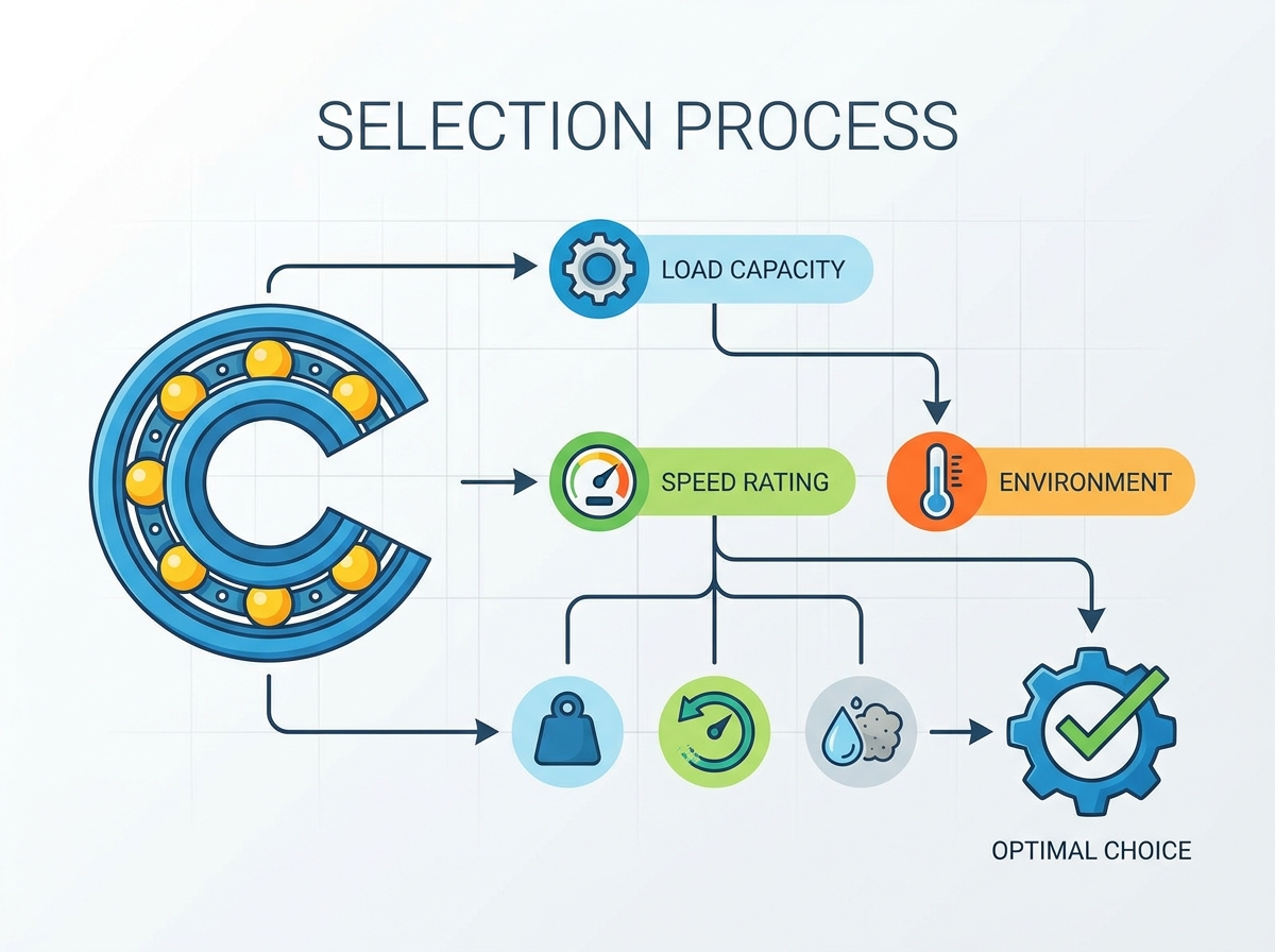
Proper bearing selection requires a rigorous, step-by-step approach to eliminate variables and ensure mechanical compatibility. Following an industry-standard methodology provides a reliable path to optimal performance. Skipping steps leads to premature failure.
- Define performance requirements and operating conditions. Do not just look at nameplate horsepower. You must calculate the actual radial and axial loads based on belt tensions, gear reaction forces, and dynamic imbalances. Map out the exact temperature profile of the operating environment.
- Select the bearing type and arrangement. Determine which bearing will locate the shaft axially and which will float to accommodate thermal expansion. A deep groove design often serves as the locating bearing due to its ability to handle bi-directional thrust.
- Determine bearing size and nominal dimensions. The shaft diameter usually dictates the bore size. From there, you select the outside diameter and width based on the required load capacity and available housing space.
- Select appropriate lubrication. Decide between grease and oil early in the design phase. Grease simplifies sealing and maintenance, while oil requires complex circulation systems but offers superior cooling for high-speed spindles.
- Verify operating temperature limits and speed ratings. Cross-reference your calculated loads and speeds against the manufacturer's dynamic load rating and limiting speed. Ensure the thermal equilibrium operating temperature remains below the lubricant's breakdown point.
- Specify fits and tolerances for both the shaft and housing interfaces. Stop using standard slip fits for everything. Analyze the rotating load vector. A rotating inner ring requires a tight interference fit on the shaft to prevent fretting corrosion.
- Choose the bearing execution. Specify the internal radial clearance, precision class, cage material, and sealing arrangement. This is where most specification errors occur on the plant floor.
- Define installation, mounting, and dismounting provisions. Establish strict installation procedures. Using a hammer and brass punch destroys the raceways before the machine ever runs. Mandate the use of induction heaters or hydraulic presses.
Defining the Operating Parameters (Problem Framing)
Analyzing Radial and Axial Load Requirements
Understanding load dynamics forms the foundation of bearing selection. The dynamic load rating (C) represents the load under which a bearing will achieve a defined basic rating life, typically one million revolutions. Engineers use this value to calculate the L10 life of the component. The static load rating (C0) defines the maximum load applied before permanent plastic deformation occurs on the raceways or rolling elements. This deformation, known as brinelling, ruins the bearing even if the shaft is not rotating.
These bearings primarily handle radial loads through the deep, uninterrupted raceway grooves that closely conform to the balls. This geometry provides excellent support for forces directed perpendicular to the shaft. The balls ride in the center of the raceway groove, distributing the stress evenly across the contact ellipse.
While they can accommodate superimposed axial (thrust) loads, this capacity has strict mechanical limits. Heavy axial loads shift the contact angle, pushing the balls closer to the edge of the raceway shoulder. If the axial load pushes the contact ellipse over the edge of the shoulder, you get severe edge loading. The lubricant film breaks down immediately, metal hits metal, and the raceway spalls. Calculating the equivalent dynamic bearing load is essential to ensure the combined radial and axial forces stay within safe operating zones.
| Load Type | Bearing Response | Failure Risk if Exceeded |
| Pure Radial Load | Balls ride in the center of the deep groove raceway. Optimal load distribution. | Standard fatigue flaking over the calculated L10 life. |
| Moderate Axial Load | Contact angle shifts slightly. Balls ride higher on the raceway shoulder. | Increased friction and heat generation. Reduced overall lifespan. |
| Heavy Axial Load | Contact ellipse breaches the raceway shoulder edge. | Immediate edge loading, lubricant film collapse, and rapid raceway spalling. |
Speed Ratings, Thermal Limits, and Frictional Torque
Speed capabilities are defined by two distinct metrics: the reference speed and the limiting speed. The reference speed represents the thermal limit. At this speed, the heat generated by internal friction exactly equals the heat dissipated by the system under standardized conditions. The limiting speed is a hard mechanical boundary dictated by cage strength, centrifugal forces, and seal design. Exceeding the limiting speed risks immediate mechanical failure, usually starting with the cage shattering.
Multiple factors influence maximum permissible RPM and frictional torque. Cage design plays a massive role. Machined brass cages withstand higher speeds and centrifugal forces than standard stamped steel cages. Lubricant viscosity must be optimized for the operating temperature. If the oil is too thick, churning friction generates excessive heat. If it is too thin, the elastohydrodynamic lubricating film collapses, causing metal-to-metal contact.
Seal friction drastically reduces speed limits. Contact seals physically rub against the inner ring to keep dirt out, generating significant drag and heat. Minimizing frictional torque is critical for energy efficiency and thermal management in high-speed applications. You must calculate the expected operating temperature by balancing frictional heat generation against the heat dissipation capabilities of the housing, shaft, and surrounding environment.
Managing Angular Misalignment and Shaft Deflection
Standard deep groove designs offer highly restricted tolerance for shaft misalignment. Typically, permissible angular misalignment ranges from merely 2 to 10 minutes of arc, depending on internal clearance and load. Operating beyond these strict limits forces the balls to run on the very edge of the raceway.
Excessive misalignment causes severe operational issues. It leads to uneven load distribution, generating high edge stresses that rapidly initiate fatigue flaking. The cage also experiences abnormal alternating forces as the balls speed up and slow down through the misaligned load zone. This accelerates wear and risks catastrophic cage fracture.
For applications prone to higher shaft deflection, such as overhung loads on a pump shaft or long unsupported fan shafts, you need mitigation strategies. You can select bearings with optimized internal geometry, utilize larger internal clearances to accommodate the tilt, or redesign the housing and shaft to improve overall rigidity.
Dimensional Constraints and Sizing (Solution Categories)
Standardizing Bore, Outside Diameter (OD), and Width
Bearing dimensions follow strict ISO metric and inch-based standardizations. These dimension series ensure global interchangeability and predictability across different manufacturers. The initial selection envelope is almost entirely dictated by the existing shaft size and the available space within the housing. You must match the required bore diameter to the shaft while ensuring the outside diameter and width fit the structural constraints of the machine design.
The ISO dimension series allows engineers to scale load capacity without changing the shaft diameter. By moving from a light series to a heavy series, the outside diameter and width increase, allowing for larger rolling elements and higher load ratings.
| ISO Series | Example (50mm Bore) | Outside Diameter (OD) | Width | Relative Load Capacity |
| 6000 (Light) | 6010 | 80 mm | 16 mm | Low - Ideal for tight spaces and light loads. |
| 6200 (Medium) | 6210 | 90 mm | 20 mm | Medium - Standard industrial workhorse. |
| 6300 (Heavy) | 6310 | 110 mm | 27 mm | High - Used for heavy shock loads and high radial forces. |
Standard vs. Thin-Section Deep Groove Ball Bearings
Standard series, such as the 6000, 6200, and 6300 lines, serve as the backbone of general industrial use. They offer a robust balance of cross-sectional area, load capacity, and durability. As the series number increases, the cross-section grows, providing progressively higher load ratings for a given bore size. You will find these in electric motors, gearboxes, pumps, and conveyor rollers.
Thin-section bearings are utilized when space and weight are critical constraints. Applications like robotics, aerospace gimbals, and medical imaging equipment rely on these specialized components. However, the reduced cross-section results in significantly smaller rolling elements and thinner rings. This trade-off drastically lowers the dynamic and static load capacities. You must perform careful load analysis to prevent premature failure when specifying thin-section designs.
Evaluating Internal Clearance, Fits, and Tolerances (Evaluation Dimensions)
The Critical Role of Radial Internal Clearance
Radial internal clearance is the total distance one bearing ring can be displaced relative to the other in the radial direction. This clearance is not a manufacturing defect; it is a vital design feature. It accommodates the reduction in clearance caused by interference fits during mounting and the thermal expansion of the rings during operation.
When you press a bearing onto a shaft, the inner ring stretches, consuming a portion of the internal clearance. When the machine runs, the inner ring usually gets hotter than the outer ring because it is attached to the heat-generating shaft. This causes differential thermal expansion, shrinking the clearance even further.
Standard clearance classes include CN (Normal), C3 (Greater than normal), C4, and C5. Selecting the correct class is paramount. C3 or C4 clearances become mandatory in high-temperature environments where the inner ring runs significantly hotter than the outer ring. They are also required when heavy interference fits are used on the shaft. If you use a CN clearance in a hot application, the internal gap goes to zero. The rolling elements get pinched, friction spikes, and the bearing seizes completely.
Shaft and Housing Fits (Bearing Interfaces)
The selection of shaft and housing fits directly alters the mounted radial internal clearance. An interference (tight) fit expands the inner ring or compresses the outer ring. A general rule of thumb is that the internal clearance is reduced by 80% of the interference fit value. A clearance (loose) fit allows for easier mounting but risks ring creep if applied incorrectly.
Fit recommendations depend heavily on rotating load conditions. If the inner ring rotates while the load remains stationary (rotating inner ring load), the inner ring requires an interference fit to prevent it from spinning on the shaft. This spinning, known as fretting, destroys the shaft geometry. Conversely, if the outer ring rotates relative to the load direction, it requires a tight fit in the housing. Non-rotating rings generally utilize a loose fit to facilitate axial movement for thermal expansion of the shaft.
Precision Classes and Runout Tolerances
Precision classes dictate the dimensional accuracy and running tolerances of the bearing. Standard classifications range from ABEC 1 through 9 (or ISO P0 through P4). ABEC 1 (P0) represents standard industrial precision, suitable for the vast majority of applications like standard electric motors and centrifugal pumps.
Higher precision classes (ABEC 5, 7, 9) drastically reduce vibration and runout at high speeds. Machine tool spindles, high-speed compressors, and precision instruments demand these tight tolerances to maintain accuracy and prevent destructive resonance. However, specifying higher precision exponentially increases manufacturing costs. Furthermore, high-precision bearings are exceptionally sensitive to contamination. If you install an ABEC 7 bearing on a rough-turned shaft or in a dirty environment, you completely waste the precision and the money.
Selecting Cages, Shields, and Seals (Features-to-Outcomes)
Cage Materials and Application Fit
The cage separates the rolling elements, preventing ball-to-ball contact and distributing the load evenly. Material selection depends entirely on the operating environment, speed, and temperature.
- Stamped Steel: The standard, cost-effective choice for general applications. It offers excellent strength and durability for moderate speeds and handles temperatures up to 300°F without issue.
- Machined Brass: Provides superior performance in high-speed, high-vibration, or large-diameter applications. Brass offers excellent sliding properties and resists the destructive forces of rapid acceleration and deceleration.
- Polyamide/Glass-Fiber Reinforced (Nylon): Delivers low friction, lightweight design, and a slight tolerance for misalignment. It operates quietly and handles start-stop applications well. However, it has strict temperature limitations, typically melting or becoming brittle if exposed to continuous heat above 250°F.
Open vs. Shielded vs. Sealed Configurations
Environmental protection dictates the choice between open, shielded, or sealed designs. Each option carries specific operational trade-offs regarding friction, speed limits, and contamination resistance.
| Configuration | Protection Level | Friction Impact | Speed Limit Impact | Best Application |
| Open | None | Lowest | None (Maximum Speed) | Enclosed gearboxes with circulating oil. |
| Shielded (ZZ) | Moderate (Dust/Debris) | Zero Added Friction | Minimal Reduction | High-speed electric motors in clean environments. |
| Sealed (2RS) | Maximum (Moisture/Dirt) | High (Contact Drag) | Significant Reduction | Conveyors, agricultural equipment, washdown areas. |
Lubrication Strategies for Deep Groove Ball Bearings (Implementation Realities)
Grease vs. Oil Lubrication
Grease serves as the default lubrication method for over 80% of deep groove applications. It is easy to apply, remains in the bearing cavity without complex sealing arrangements, and provides a physical barrier against contaminants. Pre-greased, sealed bearings offer maintenance-free operation for the life of the lubricant, drastically reducing plant maintenance hours.
Oil lubrication becomes technically necessary only when specific thresholds are crossed. Extreme speeds that exceed grease capabilities demand oil. Applications requiring significant heat dissipation also require oil bath, oil splash, or oil mist systems. Oil flows freely, carrying away heat and wear particles. However, it requires complex housing designs, active maintenance, sight glasses, and high-quality shaft seals to prevent leaks.
Specifying the Right Lubricant Properties
The primary function of any lubricant is to build an elastohydrodynamic film that separates the metal rolling elements from the raceways. The base oil viscosity at the actual operating temperature determines the thickness and strength of this film. Selecting the correct viscosity is non-negotiable. If the viscosity is too low at operating temperature, the film breaks, and you get metal-to-metal contact.
Additives and thickeners modify the lubricant for specific conditions. Extreme pressure (EP) additives are necessary for heavy loads to prevent metal-to-metal contact during shock loading. Temperature-resistant thickeners, such as Polyurea or Lithium Complex, ensure the grease maintains its consistency. If you use a standard lithium grease in a high-heat application, the oil bleeds out of the thickener rapidly, leaving behind a dry, useless clay-like substance.
Environmental Factors and Material Selection (Scalability & Compliance)
Mitigating Corrosion and Chemical Attack
Standard bearings utilize high-carbon chromium steel (52100). This material offers exceptional hardness and fatigue resistance, making it perfect for heavy loads. However, it rusts rapidly if exposed to moisture or corrosive chemicals. In washdown environments, food processing plants, or chemical applications, material substitution is required.
440C stainless steel provides moderate corrosion resistance while maintaining acceptable load capacities, though it typically carries a 20% reduction in load rating compared to 52100 steel. For extreme environments where stainless steel is insufficient, engineers utilize alternative coatings like zinc or thin dense chrome plating. Ceramic rolling elements (hybrid bearings) offer complete immunity to electrical arcing and severe chemical attack. We use hybrid bearings extensively in VFD-driven electric motors to prevent electrical fluting on the raceways.
Conclusion
- Measure your actual shaft and housing dimensions with a calibrated micrometer before ordering replacements to ensure proper interference fits.
- Calculate the operating temperature of your equipment to verify if a C3 or C4 internal clearance is required to prevent thermal seizure.
- Specify contact seals (2RS) only when the environment dictates heavy contamination, and adjust your maximum speed limits accordingly.
- Verify the base oil viscosity of your selected grease matches the actual operating temperature and speed profile of the machinery.
FAQ
Q: What happens if I use a standard clearance bearing in a high-temperature application?
A: The inner ring expands faster than the outer ring due to heat. This thermal expansion consumes the internal clearance. The rolling elements get pinched, leading to metal-to-metal contact, severe friction, rapid heat generation, and eventual catastrophic seizure.
Q: Can deep groove ball bearings handle heavy axial loads?
A: No. They handle moderate axial loads well. However, heavy thrust forces push the balls against the edge of the raceway shoulder. This creates extreme stress concentrations, breaks down the lubricant film, and causes rapid fatigue failure.
Q: Why would I choose a shielded bearing over a sealed one?
A: Shielded bearings use non-contact metal plates. They generate zero additional friction while providing moderate protection against large particulate dust. They are ideal for high-speed applications where the heat generation of a rubbing contact seal is unacceptable.
Q: How much shaft misalignment can these bearings tolerate?
A: Very little. Standard designs typically tolerate only 2 to 10 minutes of arc. Exceeding this limit causes uneven load distribution, edge loading, and accelerated wear of both the raceways and the cage structure.
Q: When is oil lubrication necessary instead of grease?
A: Oil is required when operating speeds exceed the mechanical limits of grease. It is also necessary when the application generates excessive heat that must be actively carried away from the bearing by a circulating fluid system.

 English


