Gearbox failures rarely occur without warning. The root cause is frequently a degraded bearing. Plant managers and maintenance engineers constantly struggle to differentiate between normal operational wear and critical failure indicators. They often delay replacement until secondary damage occurs to gears, shafts, or housings. You must contrast the cost of a scheduled bearing replacement against the catastrophic financial impact of a full gearbox failure and unplanned downtime.
We need a strict diagnostic framework to identify the exact threshold for replacement. This ensures that when a new bearing for Gearbox applications is required, the decision is backed by empirical evidence rather than guesswork. Monitoring specific mechanical and environmental factors allows operators to intervene before a minor component issue escalates into a complete system breakdown.
Key Takeaways
- Early Detection is Cost-Effective: Identifying acoustic, thermal, and vibrational anomalies early prevents multi-component gearbox destruction.
- Lubricant Analysis is Non-Negotiable: Visual and chemical inspections of gearbox oil and casing surfaces provide the most definitive proof of bearing spalling or flaking.
- Specification Matching Matters: Selecting a replacement requires evaluating load capacities, speed ratings, and environmental factors, not just matching part numbers.
- Precision Installation Prevents Premature Failure: Improper installation and reckless disassembly account for a significant percentage of early bearing failures; mitigation requires strict alignment, handling, and extraction protocols.
The Operational Impact of Bearing Failure in Gearboxes
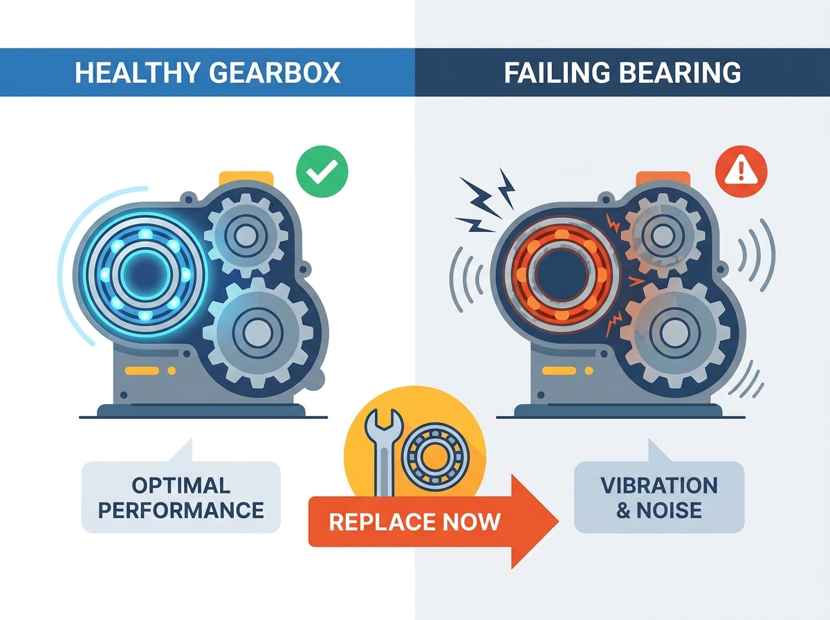
Defining a healthy gearbox baseline is the first step in any reliability program. A healthy baseline features stable operating temperatures, a consistent vibration signature, and clean lubricating oil. When equipment operates within these parameters, internal components maintain proper alignment. This ensures optimal power transmission and minimal mechanical wear. Establishing this baseline allows you to detect deviations that signal impending component distress.
When a single bearing begins to fail, it initiates a destructive cascade effect throughout the entire transmission system. As rolling elements or raceways degrade, the shaft loses its precise alignment. This shift forces gear teeth to mesh improperly. Massive loads concentrate on the edges of the gear teeth rather than distributing evenly across the face. Accelerated tooth wear follows rapidly. This eventually leads to catastrophic mechanical lock-up and the destruction of the entire gear set.
The cost-benefit analysis heavily favors proactive maintenance. Direct costs associated with scheduled labor and purchasing replacement parts are highly predictable. Reactive maintenance incurs massive indirect costs. Replacing a degraded component before it shatters preserves the integrity of the surrounding machinery.
| Parameter | Healthy Baseline | Failing Indicator | Operational Impact |
| Temperature | Stable, within 10°C of ambient | Rapid spikes, localized hot spots | Lubricant breakdown, thermal expansion |
| Vibration | Smooth, low amplitude | High amplitude, distinct defect frequencies | Shaft deflection, gear mesh misalignment |
| Oil Condition | Clear, correct viscosity | Dark, burnt smell, metallic flakes | Abrasive wear on all internal components |
| Acoustics | Consistent low hum | Grinding, squealing, rhythmic clicking | Surface fatigue, spalling, cage failure |
Indirect costs of reactive maintenance include:
- Lost production time during unplanned outages.
- Emergency shipping fees for heavy replacement components.
- Extensive labor hours required for full gearbox rebuilds.
- Potential safety hazards from catastrophic mechanical failure.
- Environmental cleanup costs from ruptured oil seals.
5 Critical Signs You Need a Replacement Bearing for Gearbox Units
Sign 1: High-Frequency Acoustic Anomalies (Grinding, Whirring, and Growling)
A healthy transmission emits a normal rushing sound or a mild, consistent hum. Diagnostic criteria for failure involve identifying abnormal acoustic signatures. High-pitched squealing, deep growling, metallic rattling, or rhythmic clicking clearly indicate that the internal geometry of the rolling elements has been compromised. You must train your ear to catch these changes early.
The root cause of these acoustic anomalies is typically surface fatigue, spalling, cage degradation, or a severe lack of lubrication. As the smooth surfaces of the raceways break down, rolling elements crash over microscopic pits. This alters the acoustic signature of the bearing for Gearbox assemblies. The noise will change pitch and volume depending on the load and speed of the application.
To properly evaluate this, maintenance personnel should use ultrasonic listening devices or mechanic's stethoscopes. These tools help isolate the noise specifically to the bearing housing, ruling out normal gear mesh frequencies. Ultrasonic tools can detect high-frequency friction long before it becomes audible to the human ear. Implement a routine route where technicians record acoustic data at the exact same location on the housing every week.
Sign 2: Elevated Operating Temperatures Beyond Baseline
Monitoring thermal output is a fundamental diagnostic practice. A sudden or gradual increase in localized heat at the bearing cap serves as a primary failure indicator. Equipment running significantly hotter than its established historical baseline requires immediate investigation. You must prevent thermal expansion from seizing the shaft and destroying the housing bore.
Increased friction generates this excess heat. Degraded rolling elements, structural cage damage, or lubricant breakdown force the mechanical system to overcome massive internal resistance. When the oil film collapses, metal-to-metal contact occurs, generating extreme localized temperatures. This heat transfers through the housing, making it detectable on the exterior surface.
To evaluate thermal conditions accurately, technicians should utilize infrared thermography or continuous Resistance Temperature Detector (RTD) sensors. Establishing a strict thermal baseline allows operators to set automated alarm limits. When taking manual IR readings, always measure from the exact same spot on the housing, preferably on unpainted metal, to ensure emissivity does not skew the data. A rise of 15 degrees above baseline warrants immediate inspection.
Sign 3: Measurable Increases in Vibration and Shaft Play
The transition from smooth operation to shaky, vibrating equipment is a definitive warning sign. Physical shaft play, whether radial or axial movement, means the component has already lost its critical internal clearances. By the time physical shaking is visible to the naked eye, severe internal damage has already taken place. The shaft will begin to deflect under load.
Wear on the races or the rolling elements themselves creates excessive clearance. This wear leads to mechanical unbalance, severe misalignment, and mechanical looseness throughout the drive train. As the clearance increases, the shaft can move off its true center of rotation. This movement destroys oil seals and allows contamination to enter the system rapidly.
Utilizing vibration analysis, specifically spectrum analysis, allows technicians to detect specific defect frequencies. You can identify Ball Pass Frequency Outer (BPFO), Ball Pass Frequency Inner (BPFI), Ball Spin Frequency (BSF), and Fundamental Train Frequency (FTF) long before physical shaking becomes perceptible. Mount accelerometers directly over the load zone of the housing for the most accurate readings. Track the trend data over time to predict the exact point of failure.
| Defect Frequency | Component Affected | Vibration Signature Characteristic |
| BPFO | Outer Ring Raceway | Impact pulses at a frequency relative to the number of rolling elements and shaft speed. |
| BPFI | Inner Ring Raceway | Higher amplitude impacts due to the load zone passing through the defect. |
| BSF | Rolling Elements (Balls/Rollers) | Modulated by the fundamental train frequency; indicates a damaged roller striking both races. |
| FTF | Cage / Retainer | Low frequency; indicates severe cage wear or broken rivets. High risk of catastrophic failure. |
Sign 4: Metallic Particulates in Lubrication and Housing Wipe-Downs
Visual and chemical signs of wear in the gearbox oil provide undeniable evidence of internal degradation. Technicians should look for shiny flakes, brass-colored dust from degrading cages, or dark, burnt-smelling lubricant. Inspecting the cleaning cloths used during routine housing wipe-downs often reveals fine, glittering metallic debris that indicates severe surface wear around the seals.
This debris originates from subsurface fatigue that leads to micro-pitting. As the metal surface fractures, it releases particulate into the oil bath and housing crevices. These hardened steel particles then act as a lapping compound, accelerating wear on all other internal components, including the gear teeth. The oil filter will catch some of this, but much of it remains suspended in the fluid.
Routine spectroscopic oil analysis and magnetic plug inspections are highly recommended. These tests quantify wear metals like iron, copper, and chromium. High concentrations of these metals confirm the immediate need for a replacement component. Pull oil samples from the active flow zone while the machine is running, not from the bottom drain plug where sludge accumulates, to get an accurate representation of suspended wear particles.
Sign 5: Unexplained Spikes in Motor Power Consumption
A failing component increases mechanical drag across the entire drive system. Consequently, the drive motor must draw more amperage to maintain the same output speed and torque. Unexplained spikes in power consumption, assuming the external load remains constant, point directly to internal mechanical binding. The motor is fighting against the friction inside the gearbox.
Internal friction and shaft misalignment force the motor to work harder, severely decreasing overall mechanical efficiency. As the rolling elements bind and skid rather than roll smoothly, the energy required to turn the shaft increases exponentially. This not only damages the gearbox but also overheats the motor windings, potentially causing a secondary electrical failure.
Integrating motor current signature analysis (MCSA) or monitoring SCADA system trends allows operators to spot these unexplained increases in power draw. Correlating power spikes with specific gearboxes helps isolate the failing component rapidly. If you see a steady upward trend in amperage draw over a few weeks with no change in production output, schedule a mechanical inspection immediately.
Decision Framework: Selecting the Optimal Replacement Bearing for Gearbox Applications
Selecting the correct replacement requires understanding the specific operational demands of the machinery. Common solution categories include spherical roller, tapered roller, and deep groove ball designs. Upgrading from the OEM standard is often necessary if historical failure data indicates that the original specification cannot handle the actual production loads. Do not blindly order the same part number if it fails repeatedly.
Evaluating load capacity is the first critical step. Ensure the dynamic and static load ratings meet or exceed current operational demands. Account for external equipment modifications, such as increased belt tension, larger pulleys, or modified overhung loads. These modifications accelerate wear on the bearing for Gearbox setups. If you have increased the throughput of the machine, the original components are likely undersized.
Evaluate sealing and shielding requirements based on the operating environment. Sealed units protect against dust, moisture, and chemical exposure. Open designs rely entirely on the gearbox oil bath. If the gearbox operates in a washdown environment or a highly dusty facility, upgrading to a sealed design or installing secondary labyrinth seals on the housing will drastically improve lifespan.
Clearance ratings play a massive role in operational success. Selecting the correct internal clearance accommodates thermal expansion during heavy operation. If a unit runs hot, a C3 or C4 clearance allows the internal components to expand without binding. Weigh the overall value influencing factors. Premium tier-one brands offer a higher upfront cost but deliver a longer Mean Time Between Failures (MTBF). Economy options might seem attractive initially, but heavy labor costs associated with frequent replacement procedures quickly negate any upfront savings.
Implementation Realities: Risks and Mitigation During Replacement
Simply installing a new component does not guarantee operational success if underlying mechanical issues are ignored. Bent shafts, warped housings, or unbalanced couplings will destroy a brand-new installation within days. Addressing these implementation risks requires strict adherence to mechanical protocols. You must inspect the entire system during the rebuild.
Avoiding collateral disassembly damage is the first mitigation strategy. Technicians must carefully extract the worn component without scoring the shaft, damaging adjacent gears, or warping the gearbox housing. Crude impact tools and open flames should be strictly prohibited during extraction. Using proper hydraulic pullers ensures the surrounding machinery remains intact. If you score the shaft during removal, the new unit will not seat correctly.
Follow these extraction steps:
- Drain all lubricant and inspect the magnetic plug for debris.
- Remove the housing cover and measure the existing endplay before disassembly.
- Use a mechanical or hydraulic puller, applying force only to the tight-fitted ring.
- Never use a cutting torch to remove a stuck ring, as this alters the metallurgy of the shaft.
- Clean the shaft and housing bore thoroughly with a non-residue solvent.
Precision installation is equally critical. Proper tools, including induction heaters and hydraulic presses, are necessary to avoid damaging the new unit during mounting. Brute force or direct hammering on the rings causes immediate micro-indentations (brinelling) on the raceways, guaranteeing premature failure. Heat the inner ring evenly using an induction heater to expand it, allowing it to slide onto the shaft without force.
Tolerance and alignment verification must follow the installation. Checking shaft and housing fits for wear ensures the new component seats correctly. Use a micrometer to measure the shaft in multiple locations to check for taper or out-of-roundness. A new unit placed in an oversized, worn housing will spin on the shaft or within the bore, failing rapidly. You may need to sleeve the shaft or bore the housing if tolerances are out of spec.
Lubrication commissioning must be executed flawlessly. Applying the correct type, volume, and viscosity of lubricant immediately upon installation prevents dry-start damage. Ensuring the oil bath is filled to the exact sight-glass level before bumping the motor is a mandatory final step. Rotate the shaft by hand to ensure the lubricant coats all rolling elements before applying power.
Conclusion
- Conduct an immediate oil analysis and vibration check on any suspect gearboxes in your facility to establish a current baseline.
- Review the historical failure data of your equipment to determine if an upgrade in load capacity or clearance rating is required.
- Audit your maintenance tool crib to ensure technicians have access to induction heaters, hydraulic pullers, and proper alignment tools.
- Consult with a mechanical specialist to source the exact replacement components required for your specific environmental conditions.
FAQ
Q: How long should a bearing for gearbox applications typically last?
A: Lifespan is calculated using the L10 life metric, representing the hours 90% of a group of identical bearings will exceed under specific loads. Operational factors like heavy contamination, poor lubrication, and extreme temperatures significantly reduce this theoretical lifespan in real-world applications. Always track actual run hours against the L10 calculation.
Q: Can I just replace the bearing, or do I need to replace the gears too?
A: You can often just replace the bearing if caught early. You must inspect the gear teeth for secondary damage. If bearing play caused severe misalignment, the gear teeth might show uneven wear, pitting, or scoring, necessitating a full gear set replacement to prevent future vibration.
Q: What is the most common cause of premature gearbox bearing failure?
A: Contamination and improper lubrication are the leading culprits. Water or particulate ingress destroys the lubricant film. This leads to metal-to-metal contact, rapid surface fatigue, and eventual mechanical seizure. Maintaining clean oil is the most effective preventative measure.
Q: How do I check for a bad bearing without dismantling the transmission?
A: Utilize non-destructive testing methods. Vibration analysis detects specific defect frequencies. Spectroscopic oil sampling reveals microscopic wear metals suspended in the fluid. Infrared thermography identifies abnormal heat generation at the housing caps. Combine these three methods for accurate diagnostics.
Q: Is it safe to run a gearbox with a noisy bearing until the next planned shutdown?
A: Running to failure carries extreme risk. While it might survive until the shutdown, a noisy component is already failing. Catastrophic lock-up can occur at any moment, potentially destroying the entire gearbox, damaging the motor, and halting production entirely. Schedule an immediate replacement.

 English


