Gearbox reliability depends heavily on the health and precise specification of its internal components. Catastrophic gearbox failures frequently originate from improper bearing selection, minor misalignment, or premature bearing degradation. When a single component degrades, the resulting vibration and misalignment can destroy gear teeth, warp shafts, and compromise the entire power transmission system. Balancing load capacity, speed ratings, and spatial constraints when specifying a bearing for gearbox repairs, upgrades, or OEM designs presents a significant engineering challenge. Unplanned downtime, compromised power transmission, and increased energy consumption pose massive financial risks to operations. This article provides an engineering-grade technical framework for evaluating gearbox bearings. We cover functional requirements, comparative types, and failure diagnostics. You will learn how to match bearing specifications to operational demands, ensuring maximum uptime and mechanical efficiency in your power transmission systems.
- Load and Alignment Dictate Selection: The primary function of any bearing for gearbox applications is to manage complex combinations of radial and axial loads while maintaining precise gear mesh alignment under torque.
- Application Specificity is Non-Negotiable: Bearing demands differ drastically between automotive standard transmissions and heavy industrial gearboxes; matching the bearing design to the specific operating environment is critical.
- Efficiency and Energy Reduction: Selecting the optimal bearing directly correlates with minimized friction torque, reducing overall system energy consumption and operational heat generation.
- Lubrication and Sealing Drive Lifespan: Up to 80% of premature gearbox bearing failures stem from lubrication degradation or particulate contamination, making environmental sealing as critical as mechanical load ratings.
- Proactive Diagnostics Prevent Catastrophe: Standardizing condition monitoring—such as vibration signature tracking and oil debris analysis—allows maintenance teams to detect micro-spalling before complete gear tooth failure occurs.
The Critical Role of a Bearing for Gearbox Performance
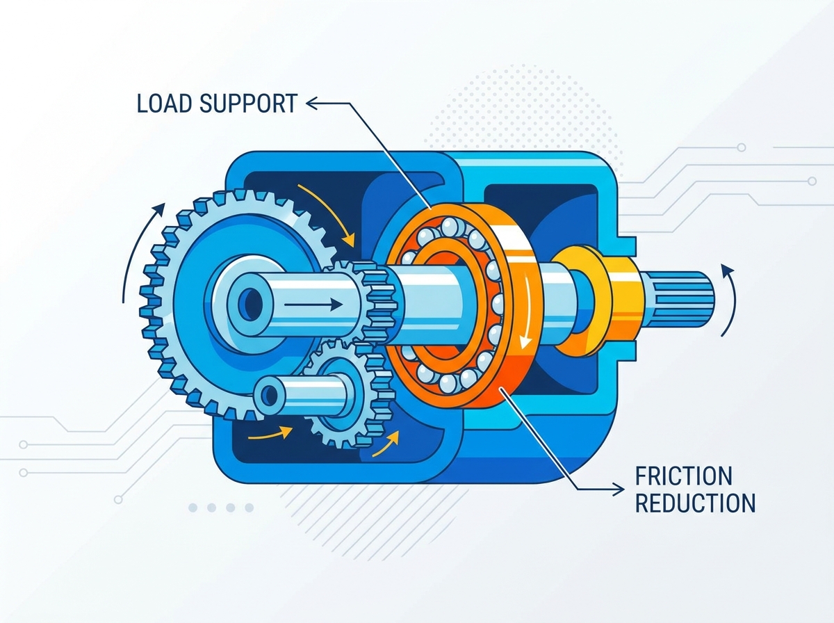
A successful bearing application in a gearbox environment achieves high rotational efficiency, long service life under high torque, dimensional stability, and thermal equilibrium. Bearings serve as the critical interface between rotating shafts and stationary housings. They must support the shaft, maintain precise gear alignment, and handle the forces generated during power transmission without generating excessive heat or friction. In heavy industrial applications, the demands placed on these components exceed standard operational parameters, requiring precise engineering and material selection.
Friction Reduction and Energy Consumption
Rolling elements minimize rotational resistance during power transmission. By replacing sliding friction with rolling friction, bearings allow shafts to turn smoothly under heavy loads. Modern bearing designs cut down on energy consumption and optimize system-wide mechanical efficiency. Optimized internal geometries, advanced cage materials, and specialized surface finishes reduce the rolling resistance. Lower friction translates directly to less heat generation, which preserves lubricant viscosity and extends the operational life of the entire gearbox. When you reduce the operating temperature by just 10 degrees Celsius, you effectively double the life of the lubricating oil.
Shaft Alignment and Gear Mesh Integrity
Bearings prevent radial and axial shaft deflection under high torque loads. Ensuring gear teeth mesh at design tolerances prevents premature wear, micro-pitting, and tooth breakage. When a shaft deflects, the gear mesh pattern shifts from the center of the tooth to the edge, causing severe stress concentrations. Rigid bearing support maintains the exact center distance between shafts. This structural rigidity is paramount in high-torque applications where even microscopic deflection can lead to rapid gear failure. Field mechanics often trace catastrophic gear tooth fractures back to a bearing that allowed just a few thousandths of an inch of radial play.
Load Management (Radial vs. Thrust)
Forces generated inside a gearbox vary significantly based on the gear type. Helical, bevel, and spur gears generate distinct radial and thrust (axial) loads. Spur gears primarily produce radial loads, pushing the shaft outward. Helical and bevel gears create both radial loads and substantial axial thrust, pushing the shaft along its axis. The selected bearing must absorb these combined forces simultaneously. Understanding the exact load vector is the first step in specifying the correct rolling element geometry.
| Gear Type | Radial Load Generation | Axial (Thrust) Load Generation | Typical Bearing Requirement |
| Spur Gear | High | None | Cylindrical Roller or Deep Groove Ball |
| Helical Gear | Moderate to High | Moderate to High | Tapered Roller or Spherical Roller |
| Bevel Gear | High | Very High | Tapered Roller (often paired) |
| Worm Gear | Moderate | Extreme | Tapered Roller or Thrust Ball Bearing |
Gearbox Bearings vs. Standard Bearings
Engineers often question whether standard bearings work in gearboxes. Gearbox-rated bearings feature specialized tolerances, optimized cage designs, and advanced metallurgy compared to general-purpose industrial bearings. Gearbox environments involve high torque, sliding friction, and heavily contaminated oil. Standard bearings may lack the specific internal clearances required to handle the thermal expansion of gear shafts. Using a purpose-built bearing for Gearbox applications ensures the component can withstand the unique stresses of power transmission. Standard off-the-shelf bearings often fail prematurely when subjected to the shock loads typical of heavy industrial gear reducers.
Types of Gearbox Bearings: A Comparative Evaluation
Industrial gearboxes, automotive drivetrains, and manual transmissions utilize various bearing designs to manage specific load profiles. Selecting the right type requires analyzing the spatial constraints, speed requirements, and load directions of the application. You cannot simply swap one type for another without re-engineering the shaft and housing tolerances.
Deep Groove Ball Bearings
Deep groove ball bearings excel in high-speed, low-to-medium load applications like standard light-duty transmissions and auxiliary shafts. They offer low friction and quiet operation. However, they possess limited axial load-carrying capacity. They remain susceptible to deformation under heavy shock loads, making them unsuitable for primary torque-bearing shafts in heavy industrial gearboxes. When installing these, mechanics must ensure the housing bore is perfectly round, as any ovality will pinch the outer ring and eliminate the internal clearance.
Cylindrical Roller Bearings
Cylindrical roller bearings manage extreme radial loads at high speeds. You will often find them on input and output shafts in heavy industrial gearboxes. Their line-contact geometry provides massive radial stiffness. The main limitation is their extreme sensitivity to shaft misalignment. Furthermore, standard designs cannot support axial thrust loads unless specified with thrust collars, such as NJ or NUP configurations. Proper installation requires heating the inner ring to expand it before sliding it onto the shaft, preventing scoring of the journal.
Tapered Roller Bearings
Tapered roller bearings handle severe combined radial and thrust loads. This capability makes them the standard choice for automotive differentials, manual standard transmissions, and heavy-duty industrial gear reducers. They require precise preload adjustment and clearance setup during installation to function correctly. They also exhibit higher initial frictional torque before run-in, necessitating careful lubrication during startup. Setting the endplay on tapered roller bearings requires using a dial indicator and shims to achieve the exact specification required by the gearbox manufacturer.
Spherical Roller Bearings
Spherical roller bearings suit high-torque applications prone to shaft deflection, housing distortion, or severe shock loads. Mining equipment and wind turbine gearboxes frequently utilize them due to their self-aligning capabilities. The trade-off involves higher internal friction and heat generation, which limits their maximum operating speeds compared to cylindrical or ball bearings. These bearings can accommodate up to two degrees of misalignment without suffering a reduction in their dynamic load rating.
Needle Roller Bearings
Needle roller bearings provide high-capacity radial load support in space-constrained layouts, such as planetary gear arrangements and standard manual transmission gear clusters. Their low cross-sectional height saves valuable space. However, they offer zero thrust capacity. They also require precision-hardened and ground shaft journals to act as inner raceways, which complicates shaft manufacturing. If the shaft surface hardness drops below 58 HRC, the needle rollers will quickly wear grooves into the metal, leading to catastrophic failure.
Technical Evaluation Criteria for Gearbox Bearing Selection
Matching bearing specifications to gearbox demands requires a systematic framework. Engineers, maintenance managers, and procurement specialists must evaluate several technical dimensions to ensure reliable operation. Guesswork during this phase leads directly to premature equipment failure.
- Determine the maximum radial and axial loads during normal operation and startup.
- Calculate the required L10 fatigue life based on the equipment's duty cycle.
- Identify the maximum operating speed and select a compatible cage material.
- Specify the internal radial clearance based on expected operating temperatures.
- Select the appropriate sealing mechanism based on the lubrication strategy.
Dynamic and Static Load Ratings (C and C0)
Interpreting manufacturer load ratings ensures the bearing handles continuous operational forces and transient startup torque without plastic deformation. The dynamic load rating (C) calculates the fatigue life of the bearing under rotating conditions. The static load rating (C0) determines the maximum load the bearing can withstand while stationary without causing permanent dents in the raceways. Gearboxes often experience severe shock loads during startup or jamming events, making the static rating just as critical as the dynamic rating. If a bearing experiences a load exceeding its C0 rating even once, it will suffer true brinelling, leading to immediate noise and rapid failure.
Operating Speeds, Thermal Limits, and Lubricant Flow
Speed ratings directly relate to cage materials and the thermal limits of the lubrication system. Brass, steel, and polyamide cages each have distinct temperature thresholds. The lubrication method—whether a simple splash bath or a forced oil circulation system—dictates how effectively heat dissipates from the bearing. Exceeding the thermal limit of the cage or the lubricant causes rapid breakdown, leading to metal-to-metal contact and catastrophic failure. Polyamide cages, for example, offer excellent elasticity and low friction but will melt if the gearbox oil temperature exceeds 120 degrees Celsius for extended periods.
Internal Clearance and Preload Specifications
Specifying the correct internal radial clearance accommodates the thermal expansion of shafts. As the gearbox reaches operating temperature, the shaft expands faster than the housing, reducing the internal clearance of the bearing. Using a C3 or C4 clearance rating prevents the bearing from seizing under high heat. Conversely, applying proper preload increases shaft rigidity and gear-mesh accuracy, which is essential for tapered roller bearings handling combined loads. A bearing installed with insufficient clearance will generate excessive heat, causing further expansion and eventual lockup.
Sealing and Shielding Configurations
Evaluating the trade-offs between open, shielded (ZZ), and contact-sealed (2RS) bearings depends on the gearbox's internal oil environment and exposure to external debris. Open bearings allow maximum oil flow but offer no protection against metallic wear particles generated by the gears. Shielded bearings deflect larger debris while allowing some oil mist to enter. Contact-sealed bearings provide maximum protection against contamination but generate higher friction and retain heat, requiring specialized internal grease. In heavily contaminated environments like cement plants, engineers often specify sealed bearings even inside enclosed gearboxes to protect against microscopic silica dust.
Common Failure Modes, Symptoms, and Diagnostic Indicators
Understanding bearing degradation in power transmission systems helps diagnose root causes and prevent catastrophic casing and gear failures. Proactive monitoring extends the life of the equipment and allows maintenance teams to schedule repairs before a complete breakdown occurs.
Fatigue Spalling and Flaking
Subsurface rolling contact fatigue (RCF) causes fatigue spalling and flaking. Over millions of cycles, microscopic cracks form below the raceway surface and eventually propagate upward, causing material to flake away. Calculating the L10 life expectancy under specific operating profiles helps predict when this fatigue will occur. Once spalling begins, the bearing generates severe vibration and must be replaced immediately to prevent shaft damage. You can often spot the early signs of spalling by examining the oil filter for tiny, shiny metal flakes.
Contamination and Lubrication Failure Modes
Visual and operational indicators reveal oil starvation, varnish buildup, thermal discoloration, and abrasive wear patterns. Fine particulates from gear wear or water ingress degrade the oil film thickness. Without adequate lubrication, the rolling elements scuff the raceways, generating excessive heat. Blue or brown discoloration on the bearing rings indicates severe thermal distress caused by lubrication failure. Water contamination is particularly destructive; even 0.1% water in the gearbox oil can reduce bearing life by up to 50% due to hydrogen embrittlement of the steel.
False Brinelling and Fretting Corrosion
Micro-movements and vibrations damage bearings during static storage, transportation, or standby operation. This phenomenon, known as false brinelling, wears depressions into the raceways matching the roller spacing. Fretting corrosion occurs when these micro-movements happen in the absence of adequate oil film, causing oxidation. Protecting standby machinery requires periodically rotating the shafts to redistribute lubricant and alter the contact points. When shipping heavy gearboxes, always lock the shafts to prevent vibration damage during transit.
Diagnostic Techniques & Symptoms
Field operators can utilize several troubleshooting techniques to catch failures early. Relying solely on human senses is inadequate for modern industrial machinery.
- Acoustic Symptoms: Distinct grinding, whining, or low-frequency rumbling often indicates outer raceway damage or roller wear.
- Thermal Monitoring: Rapid temperature spikes in the bearing housing indicate lubrication breakdown, excessive preload, or severe contamination.
- Vibration Analysis: Using acceleration enveloping detects specific bearing defect frequencies, such as Ball Pass Frequency Outer (BPFO) or Ball Spin Frequency (BSF), long before audible noise occurs.
- Oil Analysis: Monitoring metallic wear debris, including iron, copper, and lead, catches early-stage adhesive wear and cage degradation.
Conclusion
Choosing the correct bearing for gearbox environments requires a multi-faceted approach. You must balance load profiles, speeds, thermal behaviors, and structural alignment. The core decision matrix involves mapping the load direction, determining spatial and speed limits, selecting the optimal internal clearance, and defining the lubrication strategy. Implementing a rigorous selection and monitoring process ensures your power transmission systems operate reliably under heavy loads.
- Review your gearbox design blueprints to confirm exact shaft and housing dimensions before ordering replacement bearings.
- Conduct detailed oil and vibration analyses on failing units to identify the root cause of the degradation.
- Verify the required internal clearance (e.g., C3 or C4) based on the operating temperature of your specific application.
- Consult with application engineers to select the exact bearing configuration that matches your operational demands.
FAQ
Q: What is the best type of bearing for gearbox applications?
A: It depends on the design. Tapered rollers are ideal for combined axial and radial loads in heavy-duty units. Cylindrical rollers and ball bearings suit high-speed, lower-thrust applications. Spherical rollers work best where shaft deflection is present.
Q: Are gearbox bearings different from standard industrial bearings?
A: Yes. Gearbox bearings often feature specialized internal clearances, optimized cage designs, and high-purity steel formulations. These enhancements allow them to withstand high torque, sliding friction, and contaminated oil environments better than standard bearings.
Q: What are the primary symptoms of a failing gearbox bearing?
A: Primary symptoms include acoustic changes like whining or growling, increased housing temperature, and elevated vibration levels. You may also find microscopic metal flakes in the oil filter or on the magnetic drain plug.
Q: How does bearing selection impact gearbox energy consumption?
A: Optimizing bearing internal geometry, seal drag, and cage design minimizes friction torque. This reduction in rolling resistance decreases power loss, cuts overall energy usage, and lowers operating temperatures.
Q: Can I replace a ball bearing with a roller bearing in a standard transmission?
A: Modifying bearing types involves significant limitations, including physical spacing, changes in axial load capacity, and speed ratings. It often requires redesigning shaft and housing tolerances to accommodate the different geometries.
Q: What does a C3 or C4 clearance rating mean for a bearing for gearbox use?
A: A C3 or C4 rating defines a larger radial internal clearance. This extra space accommodates thermal shaft expansion as the gearbox reaches operating temperature, preventing the bearing from seizing under heavy loads.

 English


